


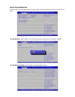


Advanced
Use [<--] / [-->] to select [Advanced] setup screen. Under this screen, you may use
[↑] [↓
] to select an item you
want to configure.
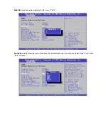
Above 4G Decoding
This option enables or disables 64bit capable devices to be decoded in above 4G address space (only if the
system supports 64bit PCI decoding). You may select “Enabled” or “Disabled”.


