background image


11

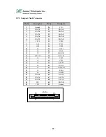
LPTA1: Parallel Connector (26 Pin 2.00mm Pitch Header) 
 

Pin No. 

Description 

Pin No.

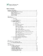
Description 

Strobe # 

Auto Form Feed 

Data0 

Error # 

Data1 

Initialize # 

Data2 

Printer Select IN # 

Data3 

10 

Ground 

11 

Data4 

12 

Ground 

13 

Data5 

14 

Ground 

15 

Data6 

16 

Ground 

17 

Data7 

18 

Ground 

19 

Acknowledge # 

20 

Ground 

21 

Busy 

22 

Ground 

23 

Paper Empty 

24 

Ground 

25 

Printer Select 

26 

KEY 


LPTA1


 2   

25  


2 6 

Содержание FW-6420

Страница 1: ...FW 6420 Series Mini Desktop VIA Eden low power Network Security Appliance User s Manual...

Страница 2: ...mitted in any form or by any means electronic mechanical photocopying recording or otherwise without the formal consent from Lanner Trademark Acknowledgments All products and or brand names stated in...

Страница 3: ...product Keep it away from wet surfaces surroundings Never push an object of any kind into this product through openings or empty slots as you may damage parts Do not attach the power supply cabling to...

Страница 4: ...6 2 8692 6060 Fax 886 2 8692 6101 E mail sales lannerinc com About this Manual This target audience of this manual includes users administrators and technicians This publication is a useful reference...

Страница 5: ...t Jack 7 COMA1 RS 232 Serial Port 1 Connector D Sub 7 VGB1 External VGA Connector 2X6 Header 2 54mm 7 PKMB1 PS 2 Keyboard Mouse Connector 2x4 Header 2 54mm 8 USBB1 Dual Connector 8 IDEA1 IDE Interface...

Страница 6: ...lth Status 34 3 10 Load Optimal Defaults 35 3 11 Supervisor User Password 36 3 12 Save Exit Setup 37 3 13 Exit Without Saving 37 Appendix A 38 A p p e n d i x B 39 Console Redirection 39 Terms and Con...

Страница 7: ...st growing network security market With this network security device you can provide a number of networking security functions that werer previously only available for the larger Enterprises such as V...

Страница 8: ...RS 232 connector Expansion Slot One PCI and One Mini PCI slot Reset One reset button for software reset RTC Internal RTC with LI battery Power One power jack 12V 5A 2 5mm Mechanical Environmental Form...

Страница 9: ...6420 Network security Platform Console cable 1 8 meters long cross over Ethernet cable 1 8 meters long straight through Ethernet cable Face panel name plate label Power adapter Power cable Drivers an...

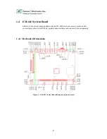
Страница 10: ...system board bundled with the FW 6420 Network security platform The succeeding sections list all EM 661 related jumper settings and connector pin assignments 1 4 1 Mechanical Dimensions Figure 2 EM 6...

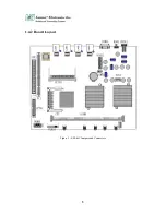
Страница 11: ...5 1 4 2 Board Layout Figure 3 EM 661 Jumpers and Connectors...

Страница 12: ...or PRJK1 3 Pin Power Input Jack COMA1 RS 232 Serial Port 1 Connector D Sub PKMB1 PS 2 Keyboard Mouse Connector VGAB1 External VGA Connector Header LPTA1 Parallel Connector USBB1 Dual USB Connector CF1...

Страница 13: ...r Detect DCDA 2 Receive Data RXDA 3 Transmit Data TXDA 4 Data Terminal Ready DTRA 5 Ground GND 6 Data Set Ready DSRA 7 Request To Send RTSA 8 Clear To Send CTSA 9 Ring Indicator RIA VGB1 External VGA...

Страница 14: ...Header 2 54mm Pin No Description 1 KBCLK 2 Ground 3 NC 4 KBDATA 5 NC 6 MSDATA 7 MSCLK 8 VCC USBB1 Dual Connector Pin No Description Pin No Description 1 USB_VCC 2 USBD0 3 USBD0 4 Ground 5 USB_VCC 6 US...

Страница 15: ...5 8 Data 10 9 Data 4 10 Data 11 11 Data 3 12 Data 12 13 Data 2 14 Data 13 15 Data 1 16 Data 14 17 Data 0 18 Data 15 19 Ground 20 NC 21 DMA REQ 22 Ground 23 IOW 24 Ground 25 IOR 26 Ground 27 IOCHRDY 28...

Страница 16: ...13 5 DATA6 30 DATA14 6 DATA7 31 DATA15 7 CE1 32 CE2 8 A10 33 VS1 9 OE 34 IOR 10 A9 35 IOW 11 A8 36 WE 12 A7 37 READY 13 CFVCC3 38 CFVCC3 14 A6 39 CSEL 15 A5 40 VS2 16 A4 41 RESET 17 A3 42 WAIT 18 A2 4...

Страница 17: ...1 Strobe 2 Auto Form Feed 3 Data0 4 Error 5 Data1 6 Initialize 7 Data2 8 Printer Select IN 9 Data3 10 Ground 11 Data4 12 Ground 13 Data5 14 Ground 15 Data6 16 Ground 17 Data7 18 Ground 19 Acknowledge...

Страница 18: ...X 25 CLK 26 RST 27 GROUND 28 3 3V 29 REO 30 GNT 31 3 3V 32 Ground 33 AD31 34 PME 35 AD29 36 RESERVED 37 Ground 38 AD30 39 AD27 40 3 3V 41 AD25 42 AD28 43 RESERVED 44 AD26 45 C_BE 3 46 AD24 47 AD23 48...

Страница 19: ...103 AC_SYNC 104 M66EN 105 AC_SDATA_IN 106 AC_SDATA_OUT 107 AC_BIT_CLK 108 AC_CODEC_ID0 109 AC_CODEC_ID1 110 AC_RESET 111 MOD_AUDIO_MON 112 RESERVED 113 AUDIO_GND 114 Ground 115 SYS_AUDIO_OUT 116 SYS_A...

Страница 20: ...s section of the manual describes the mechanical and device nomenclature of FW 6420 1 5 1 Mechanical Dimensions The illustration below identifies the physical measurements of the FW 6420 Figure 4 FW 6...

Страница 21: ...N A LAN Speed 10 Mbps On This LED indicate that the port continuously connection Ethernet Ports Link ACT Green Flash This LED will flash when the data is transmitted on the port GPIO definition VT8235...

Страница 22: ...nected to networking environment using a RJ 45 Ethernet cable DC Power Jack Power connector connected to the power adapter packed with the FW 6420 Reset Button This is software reset button It is defi...

Страница 23: ...ight of the system Step 3 Unscrew two screws from left of the system Step 4 Pull the top panel up as shown in below graph Put the top panel in a safe place System Memory Step 1 The DIMM slot has a not...

Страница 24: ...sk in the bracket and screwing four screws with the hard disk together from both sides Step 4 Install the 44 pin hard disk cable to the hard drive and screw four screws in the hard disk bracket Instal...

Страница 25: ...ot Installing the Standard PCI Expansion Card Step 1 Press the both button Step 2 Move the bracket Step 3 Take off two screws from the riser card bracket Step 4 Pull up the reiser card bracket Step 5...

Страница 26: ...nes perform various diagnostic checks while initializing the board hardware If the routines encounter an error during the tests the error will be reported in one of two ways a series of short beeps or...

Страница 27: ...n provides access to the utility s various functions Listed below are explanation of the keys displayed at the bottom of the screen ESC Exit the utility Use arrow keys to move cursor to your desired s...

Страница 28: ...Use this menu to setup power control PnP PCI Configuration This entry appears if your system supports PnP PCI PC Health Status This entry shows your PC health status if Hardware Monitor Chipset is ins...

Страница 29: ...at for p m time add 12 to the hour number e g you would enter 4 30 p m as 16 30 IDE Primary Secondary Master Slave Press PgUp or PgDn to select Manual None Auto type Note that the specifications of yo...

Страница 30: ...r Select PU PD Value F10 Save Esc Exit F1 General Help F5 Previous Values F6 Fail Safe Defaults F7 Optimized Defaults Here is a brief explanation of drive specifications z Access Mode The settings are...

Страница 31: ...sting after each drive name and select the appropriate entry Halt On During the power on self test POST the computer stops if the BIOS detects a hardware error You can tell the BIOS to ignore certain...

Страница 32: ...IOS attempts to load the operating system from the devices in the sequence selected in these items The settings are Floppy LS ZIP HDD 0 HDD 1 HDD 2 HDD 3 SCSI CDROM LAN and Disabled Swap Floppy Drive...

Страница 33: ...led Full Screen LOGO Show Show full screen logo during BIOS bootup process Seetings Enabled and Disabled 3 5 Advanced Chipset Setup When you select the CHIPSET FEATURES SETUP on the main program the s...

Страница 34: ...um Row Precharge time of the SDRAM devices on the module Active to Precharge 6T 10T This item specifies the number of clock cycles needed after a bank active command before a precharge can occur Activ...

Страница 35: ...ntains a Universal Serial Bus USB controller and you have USB 2 0 peripherals USB Keyboard Support Select Enabled if your system contains a Universal Serial Bus USB controller and you have a USB keybo...

Страница 36: ...allel port controller I O address setting The settings are 378H IRQ7 278H IRQ5 3BC IRQ7 Disabled Parallel Port Mode Select an operating mode for the onboard parallel printer port Select Normal Compati...

Страница 37: ...on is for choosing the setting in which the monitor will turn off The default setting is Suspend Always On The monitor will be turned on Suspend Off The monitor will be turned off Video Off Method Thi...

Страница 38: ...and Plug and Play compatible devices However this capability means absolutely nothing unless you are using a Plug and Play operating system such as Windows 98 If you set this field to Manual choose sp...

Страница 39: ...gs are N A C8000 CC000 D0000 D4000 D8000 or DC000 Reserved Memory Length This option specifies the size of the memory area reserved for legacy ISA adapter cards The settings are 8K 16K 32K or 64K PCI...

Страница 40: ...ing CPU temperature FAN speed and voltages It is recommended that you contact your motherboard supplier to get proper value about your setting of the CPU temperature Move Enter Select PU PD Value F10...

Страница 41: ...timal Defaults When you press Enter on this item you get a confirmation dialog box with a message similar to Pressing Y loads the default values that are factory settings for optimal performance syste...

Страница 42: ...essing Enter again When you are done the screen automatically reverts to the main screen Remember that when you use this feature the Security Option line in BIOS FEATURES SETUP will determine when ent...

Страница 43: ...quit the Setup Utility and save the user setup changes to RTC CMOS Typing N will return to Setup Utility 3 13 Exit Without Saving Select this option and press the Enter key to exit the Setup Utility w...

Страница 44: ...in Hold up time 10ms min at AC nominal input output full load Load Regulation 5 Operating temperature 0 o C to 40 o C convection Storage temperature 20 o C to 85 o C EMC EN55022 B FCC B CE spec EN5502...

Страница 45: ...sent Auto If keyboard is plug in the Controller board the Console Redirection will not display BIOS screen on remote client If keyboard is not plug in the Controller board the Console Redirection will...

Страница 46: ...sulting to the defective goods are excluded from this warranty A Improper or inadequate maintenance by the customer B Unauthorized modification misuse or reversed engineering of the product C Operatio...

Страница 47: ...press Others Item Model Name Serial Number Configuration Item Problem Code Failure Status Problem Code 01 D O A 02 Second Time R M A 03 CMOS Data Lost 04 FDC Fail 05 HDC Fail 06 Bad Slot 07 BIOS Probl...

Страница 48: ...PEXNSD01 040709 Version 1 0 Printed and published in Taiwan...

Отзывы: