8
4. INSTALLATION
WARNING:
INSTALLATION OF THE UNIT MUST BE DONE BY PERSONNEL
QUALIFIED TO WORK WITH ELECTRICITY AND PLUMBING.
IMPROPER INSTALLATION CAN CAUSE INJURY TO PERSONNEL
AND/OR DAMAGE TO EQUIPMENT. UNIT MUST BE INSTALLED IN
ACCORDANCE WITH ALL APPLICABLE CODES.
NOTICE:
The data plate is located on the inside of the hood wrap. The
Clamshell® voltage, wattage, serial number, clearance and gas
specifications are on the data plate. This information should be
carefully read and understood before proceeding with the installation.
NOTICE:
This unit is approved to be installed only on equipment which meets
NSF standards, and for which the adapter kit is provided.
4.1 Electrical Connection
The Clamshell® is supplied with a cord. The receptacle is not provided with the Clamshell®.
Follow the receptacle manufacturer’s instructions when connecting the cord to the power supply.
4.2 Gas Connection
WARNING:
BEFORE LIGHTING, USE A SOAP AND WATER SOLUTION TO TEST
ALL JOINTS FOR GAS LEAKS.
This Clamshell® is manufactured for use with the type of gas indicated on the nameplate. Contact the
factory if your type of gas does not match the nameplate data.
All gas connectors must be in accordance with local codes and comply with the National Fuel
Federal Gas Codes ANSI Z223.1 latest edition.
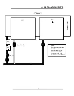
There are two gas connections involved in the installation of the Clamshell®:
The first is the gas supply to the Clamshell® itself. This connection should be made positioning
the manual shut-off valve supplied with the Clamshell® to isolate the appliance from the kitchens
main gas supply during any future service activity (See figure 1). (A service agent should be able
to shutoff and disconnect the gas supply to the Clamshell® without effecting the main gas supply
to the kitchen.) Use gas lines that have a minimum diameter of at least 1/2 an inch.
The second is the gas supply to the base appliance (the appliance to which the Clamshell® is
mounted). The Clamshell® has an external solenoid valve (the Automatic Cutoff Valve (ACV))
at the end of a flexible conduit. The ACV must be installed in line with the gas supply to the base
appliance in a location, which will ensure the ACV is not exposed to temperatures above 175
°
F
(See figure 1). Remove the cover to the ACV to ensure the correct flow direction through the
valve when making the connections. Replace the cover after the connections are complete. Use
gas lines that have a minimum diameter of at least 1/2 an inch.
NOTE: If this Clamshell® is received already mounted on a Lang griddle no further installation is
required. If this Clamshell® is a separate unit proceed to section 4.3 below.
NOTICE:
The installation of any components such as a vent hood, grease
extractors, fire extinguisher systems, must conform to their applicable
National, State and locally recognized installation standards.
4.3 Installation Instructions
Refer to the Installation instructions provided with the adapter kit, on how to connect this Clamshell®
to the griddle/charbroiler.
Содержание AGC
Страница 18: ...18 11 WIRING DIAGRAM...

