PLANNED MAINTENANCE
2-21
Fork Marking
If the fork marking is not clearly legible, it should be
remarked by the fork manufacturer, or their
representative, in accordance with paragraph 7.25.2
(ASME B56.1-2000).
Measuring Fork Thickness and Distortion
1.
Position the forklift on a flat surface, set the parking
brake and
block the wheels to prevent movement.
2.
Set the key switch to “OFF” and remove the key from
the ignition switch.
3.
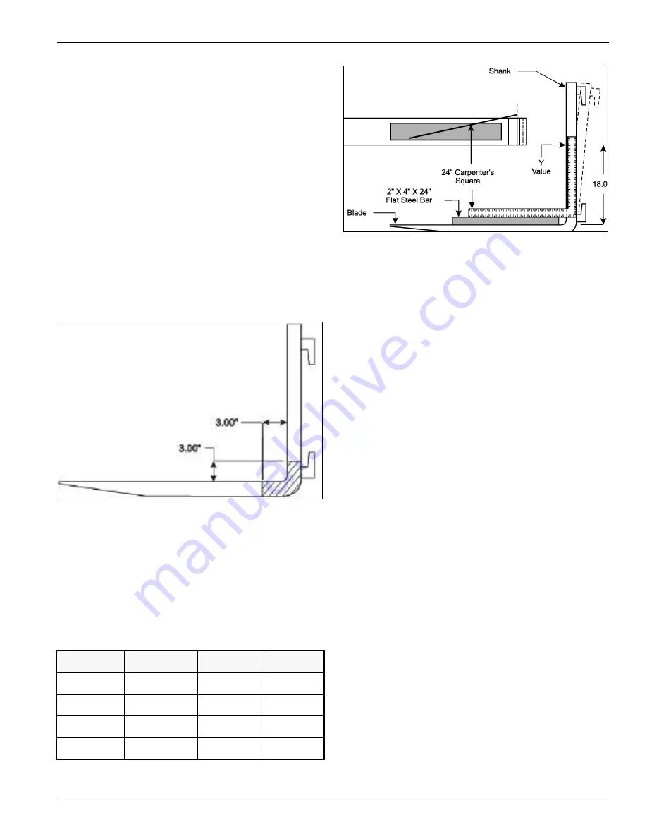
Measure fork thickness. See Figure 2-29.
4.
Compare your fork measurement to the original
thickness. 0.0625” (1.59 mm) is the maximum
acceptable wear for a standard fork size of 1-1/2”
x 4”
(38.1 mm x 101.6 mm). If the fork is worn by more
than 0.0625” (1.59 mm), the
acceptable limit, replace
both forks.
Figure 2-29: Fork Thickness
5.
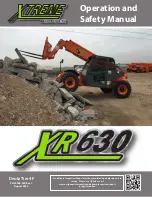
Measure the distortion distance (Y) of your forks. See
Figure 2-30.
6.
For this measurement, use a flat bar 4” x 24” (101.6
mm by 609.6 mm), that is 2” (50.8 mm) thick. Also
use a 24” (609.6 mm) carpenter’s square. See
Figure 2-30.
7.
See table below which shows the acceptable Y
distances. If the forks exceed the distance in the
chart, replace them.
Table 2-1: Acceptable Distortion Distance
Figure 2-30: Fork Tip Elevation
8.
Next, measure the elevation of each fork tip. If the
difference is more than 3/4” (19.1
mm), replace the
forks. See Figure 2-30.
9.
Check the forks for cracks, paying close attention to
the heel portion of the forks. If any cracks are found,
replace the fork.
10. Every 2,400 hours, inspect the forks with magnetic
particle or a dye penetrant inspection. If no test
equipment is available in-house, send the forks to a
qualified materials testing laboratory.
Lubricate Steer Wheel Knob
While the forklift is stationary and with the key switch
“OFF”, apply a drop or two of light machine oil where the
knob meets the steering wheel.
Spin the knob a few times and wipe off excess oil.
4500 Hours Inspection
Change Hydraulic Oil
1. The mast must be set to the normal carry position.
2.
Set the parking brake and block both of the rear
wheels.
3.
Set the key switch to “OFF” and remove the key from
the ignition switch.
4.
Open right hand door and engine compartment
cover.
5.
Clean area around the fill cap to avoid contamination.
6.
Open the fill cap. See Figure 2-7.
7.
Jack (or raise) the left side of the forklift (as viewed
from the driver’s compartment) a few
inches/centimeters to force oil to the opposite side of
the forklift. Also see Troubleshooting and Corrective
Maintenance in Chapter 3.
Blade
Length
Maximum
“Y” Value
32”
812.8 mm
3/4”
19 mm
36”
914.4 mm
31/32”
25 mm
40”
1016 mm
1 7/32”
31 mm
48”
1219 mm
1 1/2”
38 mm
Содержание Bendi B40i4
Страница 2: ......
Страница 26: ...1 20 F 581 R1 INTRODUCTION SAFETY AND INSPECTION...
Страница 100: ...3 52 F 581 R1 TROUBLESHOOTING AND CORRECTIVE MAINTENANCE...
Страница 120: ...4 20 F 581 R1 CALIBRATION AND PROGRAMMING...
Страница 129: ...ENGINE WITH FUEL SYSTEM 5 9 Figure 5 10 Fuel System Troubleshooting...
Страница 133: ...ENGINE WITH FUEL SYSTEM 5 13...
Страница 134: ...5 14 F 581 R1 ENGINE WITH FUEL SYSTEM...
Страница 140: ...6 2 F 581 R1 GM ENGINE SUPPLIER PROVIDED DOCUMENTATION...


