


3-30
F-632-1218
ASSEMBLY INSTRUCTIONS
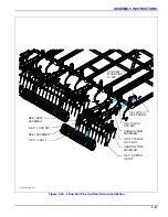
3 Row Spike and Reel Harrow
Installation
for 3 Row Spike and Reel
Harrow or
See Figures 2-67 thru 2-80
3RSD & flat reel
for placement dimensions in “Standard Specification”
section.
1.
Attach the 3 RSD arm and 3 RSD w/o arm
assemblies to the rear tube of the center and wing
frames using harrow mounting plates, 3/4-10x5-1/2
hex screws and 3/4-10 lock hex nuts
2.
Refer to Note: spike bar alignment
for proper alignment of spike bar
assemblies. Be sure they are aligned properly on
both right and left side of each section.
3.
Attach spike bars to spike harrow arm assemblies
per placement drawings using bar clamps, bar clamp
plates 1/2-13 x 3 hex head cap screws, or bar clamps
w/ tabs, 1/2-13 x 1-1/4 hex head cap screws, and hex
lock nuts.
4.
See spring assembly adjustment for initial setting in
“Operating Section”.
5.
Attach reel assembly or flat reel assembly to 3 RSD
arm assemblies using 5/8-11 u-bolts and 5/8-11 hex
lock nuts.
6.
Attach flat bar reels with angled blades as shown
Figure 3-22: Flat Reel
7.
for 3 Row Spike and
Reel Harrow or
3RSD &
flat reel
placement dimensions of spike harrow arms,
spike bars, and usage of bar clamps or bar clamps w/
tabs.
8.
Refer to the “3 Row Spike and Reel Adjustments” in
Operation and Maintenance section for spike angle
and spring adjustments
.
)5217