background image

4-9 HUB AND DRUM MAINTENANCE

4-9.1

Clean and inspect the brake drums

whenever relining the brakes. To be suitable

for further service, the brake drum should

pass the following checks.

a.

The brake surface should be free of scoring,

excessive heat checks and cracks.

b.

The brake surface diameter should be within

the maximum diameter cast or stamped on

the drum.

c.

The mounting holes and pilot must be round

and true.

d.

The mounting surface must be clean and

flat.

WARNING

FAILURE TO REPLACE FAULTY

BRAKE DRUMS WILL RESULT IN AN

UNRELIABLE BRAKING SYSTEM, AND

MAY LEAD TO AN ACCIDENT.

4-9.2

It may be necessary to turn or resurface

the braking surface to remove small heat

checks or other surface defects resulting

from normal use.

a.

The maximum diameter cast into the back

plate portion of the brake drum is the maxi-

mum diameter or discard diameter to which

the brake drum may be turned or worn and

still be usable. If any portion of the brake sur-

face exceeds the maximum diameter it must

be discarded. The maximum is .120 over the

nominal new diameter unless stated other-

wise on the casting. The maximum diameter

cast into the brake drum supersedes all pub-

lished information.

b.

When resurfacing a drum, allow at least

0.040 inches under the maximum diameter for

additional wear.

WARNING

TURNING A BRAKE DRUM BEYOND

0.040 INCHES UNDER THE MAXIMUM

DIAMETER WILL RESULT IN A

WEAKER BRAKE DRUM AND MAY RE-

SULT IN AN ACCIDENT.

4-9.3

Replacement of the brake drum is re-

quired if any of the following conditions exist:

a.

The brake drum is cracked.

b.

The brake surface is heat checked, grooved

or worn beyond the rebore limit or the maxi-

mum diameter.

c.

The back plate is cracked.

d.

The bolt holes are elongated.

e.

The brake drum has been severely over-

heated.

f.

The brake drum is out-of-round.

CAUTION

REPLACE BRAKE DRUMS IN PAIRS

TO ACHIEVE THE SAME BRAKING

POWER ON BOTH WHEELS AND

MAINTAIN AN EVEN BRAKING LOAD

ON THE AXLE. FAILURE TO DO THIS

MAY SIGNIFICANTLY REDUCE THE

PERFORMANCE, SERVICE LIFE,

AND/OR SAFETY OF YOUR VEHICLE.

4-9.4

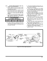
Replace the hub and drum as follows

(See Figure 4-14):

a.

Remove the brake drum

(See Figure 4-14)

.

It may be necessary to release the slack ad-

juster.

b.

Remove hub cap and catch lubricant in a

pan.

c.

Remove outer spindle nut, spindle locking

washer, inner spindle nut, and bearing. Re-

move hub from axle.

d.

Using an appropriate driver, remove inner

bearing cone, and seal.

e.

Using an appropriate driver, remove bearing

cups from hub.

f.

Check that the hub cavity is clean. If the hub

is to be reused, clean it thoroughly.

4-21

Содержание 825A

Страница 1: ...MODEL 825A 835 DETACHABLE TRAILER OPERATOR S MANUAL 1900 North Street Marysville KS 66508 785 562 5381 F 332 0503 05 03...

Страница 2: ...fective within a sixty 60 month warranty period prorated on the following basis One 1 Year 100 Three 3 Years 70 Five 5 Years 50 Two 2 Years 80 Four 4 Years 60 All Bottom Dump and Industrial and Utilit...

Страница 3: ...MODEL 825A 835 DETACHABLE TRAILER OPERATOR S MANUAL PURCHASED FROM DATE ADDRESS PHONE NO SERIAL NO i...

Страница 4: ...olved in individual prob lems between you your dealer or Landoll Manufacturing To contact NHTSA you may either call the Auto Safety Hotline toll free at 1 800 424 9393 or 366 0123 in Washington D C ar...

Страница 5: ...SEMITRAILER 3 14 3 14 SECURING THE LOAD 3 14 3 15 PREPARATION FOR TRANSPORT 3 15 3 16 UNLOADING THE SEMITRAILER 3 15 3 17 WORK LIGHT OPTION 3 16 3 18 WINCH CONTROLS OPTION 3 16 3 19 AIR RIDE OPERATIO...

Страница 6: ...IF NOT AVOIDED WILL RESULT IN DEATH OR SERIOUS INJURY WARNING WARNING INDICATES A POTENTIALLY HAZARDOUS SITUA TION WHICH IF NOT AVOIDED COULD RESULT IN DEATH OR SERIOUS INJURY CAUTION CAUTION INDICAT...

Страница 7: ...YOU HAVE ANY QUESTIONS CONTACT LANDOLL CORPORATION 1900 NORTH STREET MARYSVILLE KANSAS 66508 or phone 785 562 5381 or 800 428 5655 or FAX 785 562 4893 SECTION 5 is a troubleshooting guide to aid in di...

Страница 8: ......

Страница 9: ...ICAL HOOKUP 7 WAY CONNECTOR AIR HOOK UP COLOR CODED GLAD HANDS SPECIFIC BOLT TORQUES AIR RIDE SUSPENSION EQUALIZER BEAM PIVOT AND ADAPTER BOLTS DESIGNATED W NEWAY ON BOLT HEAD 800 FT LBS DESIGNATED W...

Страница 10: ...65 81 90 112 9 16 12 55 62 80 100 110 137 9 16 18 60 75 90 112 130 162 5 8 11 75 94 110 137 170 212 5 8 18 85 106 130 162 180 225 3 4 10 130 162 200 250 280 350 3 4 16 150 188 220 275 320 400 7 8 9 12...

Страница 11: ...146 75 85 16 115 125 202 218 109 121 20 160 180 248 272 213 237 24 185 215 303 327 238 262 32 250 290 310 340 LANDOLL CORPORATION HYDRAULIC FITTING TORQUE SPECIFICATIONS 37o JIC ORS ORB REV 10 97 THIS...

Страница 12: ......

Страница 13: ...ing emergency valve or by disconnecting the emergency glad hands 3 1 2 Air Brake System The air brake system of the semitrailer is oper ated from the towing vehicle after coupling The towing vehicle s...

Страница 14: ...3 2 Figure 3 1 Model 825 Trailer Terminology Figure 3 2 Service Hookups...

Страница 15: ...tart the semitrailer hydraulic power engine Use the TRAILER LIFT lever See Section 3 9 to raise or lower the kingpin plate suffi ciently to set proper coupling height Drain all air and moisture from t...

Страница 16: ...source of coupling failure repair before continuing and repeat Section 3 3 3 and 3 3 4 3 3 5 Check that the towing vehicle couples securely to the semitrailer before setting tow ing vehicle and semitr...

Страница 17: ...3 1 3 5 4 Check the operation of all lights and sig nals on the semitrailer for proper response to switch positions stop right turn left turn and clearance Check operation of remote function if presen...

Страница 18: ...3 6 Figure 3 3 Hydraulic Controls...

Страница 19: ...rning the tractor keyswitch on The warning lamp should go off once the semitrailer exceeds 4 mph If the warning lamp does not go off a fault exists in the semitrailer ABS Once the vehicle speed exceed...

Страница 20: ...ver 3 8 5 Attempt to pull the tractor forward If the tractor uncouples verify all service lines are disconnected and semitrailer wheels are chocked If tractor does not disconnect re peat Section 3 8 4...

Страница 21: ...1 DO NOT OVERLOAD EXTENSIONS OVERWIDTH RATINGS ARE GIVEN IN STANDARD SPECIFICATIONS 2 DO NOT SECURE LOAD TO OVER WIDTHS OR UNDERCARRIAGE SE CURE LOAD FRAME TO MOUNTED D RINGS OR GOTCHAS LOCATED IN TH...

Страница 22: ...3 10 Figure 3 5 Swingout Outrigger Platform Extension...

Страница 23: ...RDS 2 CENTERLINE OF TRACKS OR TIRES MUST BE LOADED ON THE MAIN DECK NOT ON EXTENSION BRACK ETS FAILURE TO LOAD EXTENSION BRACKETS PROPERLY CAN RESULT IN EQUIPMENT DAMAGE AND PER SONAL INJURY 3 11 4 Ce...

Страница 24: ...3 12 Figure 3 6 Gooseneck Attachment to Frame...

Страница 25: ...art operation of hydraulic power sys tem 3 12 4 Move TRAILER LIFT lever to the up position raising the semitrailer 3 12 5 Push LOAD BLOCK RELEASE BUT TON raising the load blocks up 3 12 6 Push carrier...

Страница 26: ...ons in Section 3 14 3 14 SECURING THE LOAD WARNING DO NOT ALLOW SLACK IN TIEDOWNS A SHIFTING LOAD MAY CREATE ENOUGH MOMENTUM TO BREAK HI TEST CHAINS OR STRAP TIES SLACK IN TIEDOWNS MAY RESULT IN DAM A...

Страница 27: ...arance is obtained to seat the load blocks CAUTION FAILURE TO SUPPORT THE SEMI TRAILER FULLY ON THE LOAD BLOCKS DURING TRANSPORT AND PARKING MAY RESULT IN DAMAGE TO THE LOAD THE SEMITRAILER AND POSSIB...

Страница 28: ...CONTROL PROPERTY DAMAGE INJURY OR DEATH CAN RESULT 3 FAILURE TO LEAVE AT LEAST FIVE WINCH CABLE WRAPS ON THE WINCH CABLE SPOOL COULD ALLOW THE CABLE TO COME OFF THE SPOOL RESULTING IN SERIOUS PERSONAL...

Страница 29: ...TCH HANDLE has two positions See Figure 3 7 DISENGAGE When the handle is placed is this position the winch is disengaged This allows the spool to free wheel and the winch is not affected by use of the...

Страница 30: ...When reducing from a higher to a lower setting first reduce to some pressure less than that desired then bring up to the desired point 3 Push lockring on adjusting knob downward to lock pressure sett...

Страница 31: ...en sion remove the front most pin from the bracket Lower the extension to a horizontal position Replace the front most pin in its new position To use the extension as a bulkhead simply return the exte...

Страница 32: ...l devices such as re mote controls may be powered from the auxiliary circuit while the semitrailer is stationary Back up power to the ABS is supplied through the stop lamp red circuit No 4 pin on the...

Страница 33: ...riodically check drain holes in the bot tom of the relay valve for trailers with air brakes and storage compartments They must be open at all times to avoid moisture en trapment 3 23 HOT WEATHER OPERA...

Страница 34: ......

Страница 35: ...ust be repaired or replaced at once Deter mine the cause of any binding or hydraulic leakage at once Correct the problem before using the tractor or trailer b Use the troubleshooting section Chapter 5...

Страница 36: ...4 2 Figure 4 1 Lubrication Points...

Страница 37: ...e grease and oil from all parts of the trailer Rinse degreasing solution off with cold water c Inspect semitrailer for cause of any reported troubles WARNING PAINT THINNER AND OTHER SOL VENTS ARE FLAM...

Страница 38: ...I AIR RIDE SUSPENSION I T I T HYDRAULIC OIL I I R 1 c HYDRAULIC FILTER R R HOSES I I I WINCH GEAR CASE OPT I I 2 c I Inspect R Replace T Tighten Adjust Torque L Lubricate C Clean NOTES a Perform at th...

Страница 39: ...ting chipping or other damage 4 3 GOOSENECK FRAME AND DECK 4 3 1 Repairing Structural Defects If any structural defect is found the fault must be corrected before further use of the vehicle To continu...

Страница 40: ...4 6 Figure 4 2 Model 825A Wiring Diagram...

Страница 41: ...T DS20 IDENTIFICATION CENTER DS21 LEFT TURN YELLOW DS22 RIGHT TURN YELLOW DS23 ABS MALFUNCTION INCATOR YELLOW DS24 LEFT REAR SIDE MARKER RED DS25 RIGHT REAR SIDE MARKER RED 825A 835 WIRING PARTS LIST...

Страница 42: ...nctioning voltage regula tor Locate the source of the problem and re pair System grounds must be grounded to bare metal surfaces Paint grease wax and other coatings act as insulators Replace ment lamp...

Страница 43: ...4 9 Figure 4 4 Tandem Axle Air Ride Suspension System...

Страница 44: ...4 10 Figure 4 5 Tandem Axle W Flip Air Ride Suspension System...

Страница 45: ...is cor rect Consult Landoll Service Center if correct height cannot be obtained f Loosen the 1 4 adjusting lock nut located on the adjusting block allowing the control arm to move approximately 1 inc...

Страница 46: ...or negative camber align ment can be checked as follows a Remove wheel hub and bearing assem blies b Place a 3 point axle gauge against the front side of the axle and adjust each axle gauge point to t...

Страница 47: ...4 13 Figure 4 8 Checking Axle Alignment Figure 4 9 Examples of Camber...

Страница 48: ...es must be replaced immediately b Air Ride Suspension Axles The air ride suspension is aligned and ad justed at the factory and it should not be necessary to align the axles If however it does become...

Страница 49: ...oir daily A drain cock on the bottom of each air reservoir vents the tank to drain collected water and oil If held open air pressure in the tanks is relieved causing the emergency or parking brakes to...

Страница 50: ...e inlet ports by loosening the service chamber clamp bands and rotating center housing such that ports are located according to alignment marks made during disassembly then retighten the clamp bands 3...

Страница 51: ...retainers from the rollers 5 Press down on the bottom brake shoe and remove the lower cam roller Lift the top shoe and take out the top cam roller 6 Lift out the shoe retractor spring which is now fre...

Страница 52: ...4 18 Figure 4 12 Axle and Brake Assembly...

Страница 53: ...his rotation indicates that an excessive clearance condition has been determined by the slack adjuster and it is making an adjustment to compensate On each subsequent brake release the amount of adjus...

Страница 54: ...and cut rod to length 13 If the push rod is not fully engaged in clevis body install a new push rod cut to length 14 Install the slack adjuster on the cam shaft 15 Rotate the manual adjuster shaft CW...

Страница 55: ...ormation b When resurfacing a drum allow at least 0 040 inches under the maximum diameter for additional wear WARNING TURNING A BRAKE DRUM BEYOND 0 040 INCHES UNDER THE MAXIMUM DIAMETER WILL RESULT IN...

Страница 56: ...ghtening the nut until it is snug against the outer bearing cone Remove the hub support allowing the hub to rest on the bearings l Install and adjust bearings See Section 4 10 Wheel Bearing Lubricatio...

Страница 57: ...eel to in sure proper seating of the bearings and cups in the wheel hub f Loosen the inner adjustment nut so that the wheel will turn freely g Retighten the inner adjustment nut to 50 ft lbs while rot...

Страница 58: ...from be tween duals 4 11 2 Tire Matching Both tires on the same spindle must be the same size in order to properly distribute the load and braking forces between them The tire must be mounted on a rim...

Страница 59: ...4 25 Figure 4 18 Mounting Tires and Wheels Figure 4 19 Stud Tightening Sequence...

Страница 60: ...he semitrailer is going to be out in the weather for any length of time it is advisable to oil the winch cable to prevent untimely rusting and deterioration of the cable See Table 4 1 for lubrication...

Страница 61: ...ire loose clean and tighten ground LIGHTS FLICKERING Wires shorted or loose locate insulate replace or tighten Grounding through fifth wheel locate broken ground wire tractor or semitrailer LIGHTS DIM...

Страница 62: ...verload loads are above rated tire capacity DO NOT load above rated tire capacity SHOULDER TREAD WEAR ONE SHOULDER Axle damage straighten or replace axle Axles not parallel check axle alignment OVERAL...

Страница 63: ...R TRACKING PROBLEMS TRACKS TO ONE SIDE Axle alignment re align axle TRACKS TO EITHER SIDE Broken or bent springs or equalizers replace defective parts Axles not parallel realign axles AIR RIDE HEIGHT...

Страница 64: ...e drum Broken brake chamber spring replace spring Brake chamber pushrod binding re align brake chamber bracket Air brake line loose or broken tighten or repair UNEVEN BRAKES See SINGLE BRAKE DRAGGING...

Страница 65: ...AKES GRABBING Grease on brake linings reline brakes Brake rigging binding align brakes or replace bent parts Defective brake valve on tractor repair or replace valve Defective relay emergency valve re...

Страница 66: ...e drums check for defective or misadjusted brake linings distorted or over machined drums Also check for op erating conditions or loads that create severe or excessive brake applications BRAKES PULL T...

Страница 67: ...sive load check unit specifications for load limits Slipping or broken pump drive repair or replace couplings Check for alignment SYSTEM OPERATES ERRATICALLY Air in the system check suction side of sy...

Страница 68: ...l replace clean or add oil as needed Water in oil replace oil Air leaks check suction line and component seals for suction leaks Replace defective parts NOISY PUMP Low incorrect foamy oil replace clea...

Страница 69: ...NOTES 5 9...

Страница 70: ......

Отзывы: