3-15 PREPARATION FOR TRANSPORT
3-15.1
After securing the load, following the
steps as outlined in
Section 3-14,
back the
tractor until the gooseneck is within a few
inches of the front of the semitrailer.
3-15.2
Using the
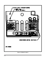
TRAILER LIFT
lever, to lower
or raise the gooseneck, as necessary, until
the load hooks are aligned with the receiver
hooks.
3-15.3
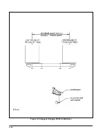
Slowly back the gooseneck into the
semitrailer until the gooseneck hooks guide
into place.
3-15.4
Using the
TRAILER LIFT
lever, lift the
semitrailer until the semitrailer rests fully on
the load blocks.
3-15.5
Reconnect the electrical and air service
lines from the semitrailer to the gooseneck.
The 7 pole electrical connector attaches to
the receptacle in the side of the gooseneck.
Disconnect dummy gladhands to connect
service and emergency air hoses to their re-
spective gladhand on the side of the goose-
neck.
3-15.6
Using the
TRAILER LIFT
lever, raise
the semitrailer until load carrier locks into
place and enough clearance is obtained to
seat the load blocks.
CAUTION
FAILURE TO SUPPORT THE SEMI-
TRAILER FULLY ON THE LOAD
BLOCKS DURING TRANSPORT AND
PARKING MAY RESULT IN DAMAGE
TO THE LOAD, THE SEMITRAILER,
AND POSSIBLE SERIOUS INJURY OR
DEATH TO INDIVIDUALS NEAR THE
SEMITRAILER.
CAUTION
THE GOOSENECK MAY BE USED IN
THE LOWERED OR RAISED POSI-
TIONS TO AVOID LOW CLEARANCE
OBSTACLES OR HIGH CENTERING.
NEVER EXCEED 2 MILES AN HOUR
WHEN TRANSPORTING THE SEMI-
TRAILER IN THIS MANNER.
3-16 UNLOADING THE SEMITRAILER
3-16.1
Prepare to unload the semitrailer by fol-
lowing the steps outlined in
Section 3-12.
3-16.2
Remove the chains and binder or the
tie-straps from the load.
3-16.3
Drive the load off the front of the semi-
trailer or remove a stationary load by means
of a forklift, crane, or other means satisfac-
tory to the constitution of the load.
3-16.4
Reattach the gooseneck to the semi-
trailer following the steps as outlined in
Sec-
tion 3-15.
WARNING
WHEN REMOVING LOAD, INSURE
THAT THE LOAD IS STEERING
STRAIGHT SO IT DOES NOT MANEU-
VER OFF THE SIDE OF THE SEMI-
TRAILER. FAILURE TO SO COULD RE-
SULT IN DAMAGE TO EQUIPMENT, IN-
JURY, OR DEATH.
3-16.5
Shut down hydraulic power system.
3-15
Содержание 825A
Страница 3: ...MODEL 825A 835 DETACHABLE TRAILER OPERATOR S MANUAL PURCHASED FROM DATE ADDRESS PHONE NO SERIAL NO i...
Страница 8: ......
Страница 12: ......
Страница 14: ...3 2 Figure 3 1 Model 825 Trailer Terminology Figure 3 2 Service Hookups...
Страница 18: ...3 6 Figure 3 3 Hydraulic Controls...
Страница 22: ...3 10 Figure 3 5 Swingout Outrigger Platform Extension...
Страница 24: ...3 12 Figure 3 6 Gooseneck Attachment to Frame...
Страница 34: ......
Страница 36: ...4 2 Figure 4 1 Lubrication Points...
Страница 40: ...4 6 Figure 4 2 Model 825A Wiring Diagram...
Страница 43: ...4 9 Figure 4 4 Tandem Axle Air Ride Suspension System...
Страница 44: ...4 10 Figure 4 5 Tandem Axle W Flip Air Ride Suspension System...
Страница 47: ...4 13 Figure 4 8 Checking Axle Alignment Figure 4 9 Examples of Camber...
Страница 52: ...4 18 Figure 4 12 Axle and Brake Assembly...
Страница 59: ...4 25 Figure 4 18 Mounting Tires and Wheels Figure 4 19 Stud Tightening Sequence...
Страница 69: ...NOTES 5 9...
Страница 70: ......


