


3-1.5
Electrical
The only electrical operation required of the
operator is interconnection of the towing vehicle
electrical cable plug with the semitrailer electrical
receptacle.
It is necessary that the tractor blue wire be
connected to the appropriate electrical source on
the tractor.
3-1.6
Hydraulic
Most controls are located on the driver’s side
of the trailer. A hydraulic pump must be coupled to
the trailer hydraulic system, or the optional hydrau-
lic engine package started, before any hydraulic
controls can function. The hydraulic system is de-
signed to operate at 2500 psi maximum pressure
and approximately 17 gpm flow capacity.
3-2 PRE-COUPLING OF SEMITRAILER AND TRACTOR
3-2.1
Slowly back the tractor/truck (towing ve-
hicle) up to the front end of the semitrailer so
the kingpin of the semitrailer is centered be-
tween the tractor fifth wheel jaws. Stop the
towing vehicle just inches ahead of the semi-
trailer. Set tractor parking brake.
3-2.2
Check the semitrailer king pin plate. It
should be in a horizontal position. The king
pin plate should be the same height, to
slightly lower, than the latch area of the fifth
wheel plate of the towing vehicle. If neces-
sary, connect the tractor hydraulic lines, or
start the semitrailer hydraulic power engine.
Use the
TRAILER TILT
lever
(See Section
or hydraulic landing gear
(See Section
to raise or lower the kingpin plate
sufficiently to set proper coupling height.
Drain all air and moisture from the towing ve-
hicle air brake system following towing vehi-
cle manufacturer’s instructions.
3-2.3
Connect the service and emergency air
hoses of the towing vehicle to their respec-
tive gladhand on the front of the semitrailer;
red emergency line to the gladhand with the
“EMERGENCY”
tag, and the blue service
line to the gladhand with the
“SERVICE”
tag
(See Figure 3-3).
Chock the semitrailer
wheels before activating the semitrailer air
supply valve in the towing vehicle. Set the
parking brakes.
WARNING
FAILURE TO CHOCK SEMITRAILER
WHEELS COULD ALLOW MOVEMENT
OF THE SEMITRAILER RESULTING IN
SERIOUS PERSONAL INJURY, DEATH,
OR DAMAGE TO PROPERTY IN ITS
PATH.
3-2.4
Check the air brake operations of the
semitrailer as follows:
a.
Apply brakes and inspect brake action on all
wheels for prompt application.
b.
Release brakes. All brakes should release
immediately. Air pressure should discharge
quickly from the relay emergency valve.
c.
Disconnect the emergency air line from the
semitrailer gladhand. Trailer brakes should
promptly set.
d.
Re-connect the emergency air line to the
semitrailer and activate the semitrailer air
supply valve. The semitrailer brakes should
set.
3-3
Figure 3-3 Service Hookups
Содержание 600B Series
Страница 3: ...MODEL 600B SERIES SEMITRAILER OPERATOR S MANUAL PURCHASED FROM DATE ADDRESS PHONE NO SERIAL NO i...
Страница 8: ......
Страница 12: ......
Страница 14: ...3 2 Figure 3 1 Front Trailer Terminology Figure 3 2 Rear Trailer Terminology...
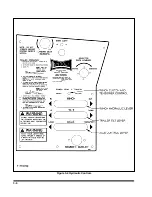
Страница 18: ...3 6 Figure 3 4 Hydraulic Controls...
Страница 26: ...3 14 Figure 3 7 Steps for Loading and Unloading...
Страница 32: ...3 20 Figure 3 10 Dock Leveler Operation...
Страница 38: ...3 26 Figure 3 14 Rear Impact Guard and Antilock Brake System...
Страница 42: ...4 2 Figure 4 1 Lubrication Points...
Страница 48: ...4 8 Figure 4 3 600B Wiring Diagram...
Страница 49: ...4 9 Figure 4 4 Remote Wiring Diagram...
Страница 52: ...4 12 Figure 4 5 Tandem Axle Air Ride Suspension System Figure 4 6 Air Ride Height Adjustment...
Страница 54: ...4 14 Figure 4 7 Triple Axle Air Ride Suspension System...
Страница 57: ...4 17 Figure 4 9 Checking Axle Alignment Figure 4 10 Examples of Camber...
Страница 61: ...4 21 Figure 4 13 Axle and Brake Assembly...
Страница 71: ...4 31 Figure 4 21 Dock Leveler Leg Assembly...
Страница 73: ...4 33 Figure 4 22 Crank Landing Gear Assembly...
Страница 84: ...NOTES 5 10...


