Landoll 345F Скачать руководство пользователя страница 49

MAINTENANCE AND LUBRICATION

4-19

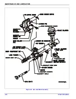
Wheel Bearing Lubrication 
and Adjustment

With trailer sitting level, the oil level must be checked 
daily and maintained between the “ADD” and “FULL” 
lines on the hub cap window. Check for cracked 
windows, missing filler plugs, and oil leaks. Add hub oil 
through the “POP-IN” filler plug located in the center of 
the hub windows. Re-install the “POP-IN” plugs after 
filling each hub. Adjust wheel bearings and change oil 
every 50,000 miles or with each brake lining 
replacement, which ever occurs first.
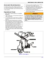
Adjustment

1.

With a drain pan under the hub cap, remove the hub 
cap assembly allowing oil to drain.

2.

Lift the wheel off of the ground.

3.

Adjust slack adjuster to eliminate brake drag during 
tire/wheel rotation.

4.

Remove outer lock nut and inner nut and lock 
washer.

5.

Tighten the inner adjustment nut to a minimum of 75 
ft.-lbs., while rotating wheel to insure proper seating 
of the bearings and cups in the wheel hub.

6.

Loosen the inner adjustment nut so that the wheel 
will turn freely.

7.

Retighten the inner adjustment nut to 50 ft.-lbs. while 
rotating the wheel, to properly position the bearings 
for the final adjustment.

8.

Loosen the inner adjustment nut 1/3 turn.

9.

Install the spindle nut lock washer so that the dowel 
on the inner nut will align with a hole in the lock 
washer and the washer tang fits in the spindle 
keyway.

10. Install the outer lock nut and tighten to 250-300 

ft.-lbs. End-play of .001" to .010" must be present in 
the adjusted wheel bearing assembly.

DANGER

11. Install the hub cap with a new gasket and fill with oil 

to the full mark 

(See Table 4-1.)

12. Adjust brakes according to 

“Brake Adjustment” on 

page 4-12.

13. Check hub oil level after the wheel has set level in 

one position for a few minutes to allow the oil to work 
into the bearings.

Failure to torque the outer lock nut properly could 
cause the wheel to come off during vehicle 
operation resulting in property damage or loss of 
life.

Содержание 345F

Страница 1: ...F 944 1017 10 2017 LANDOLL CORPORATION 1900 North Street Marysville Kansas 66508 785 562 5381 800 428 5655 WWW LANDOLL COM Model 345F Trailer Operator s Manual...

Страница 2: ......

Страница 3: ...ing Vehicle Services to the Trailer 3 3 Towing Vehicle and Trailer Hook Up and Check Out 3 4 Towing the Trailer 3 4 Parking the Trailer 3 5 Uncoupling Towing Vehicle from Trailer 3 5 Winch Controls 3...

Страница 4: ...Unit 4 11 Caging the Power Spring in the Spring Chamber 4 11 Uncaging the Power Spring in the Spring Chamber 4 11 Removal of Brake Unit 4 11 Installation of Brake Unit 4 11 Tandem Relay Valve Maintena...

Страница 5: ...F 944 1017 Edition iii 5 Troubleshooting Electrical 5 1 Tires Wheels Suspension 5 2 Brakes 5 3 Brake Drums 5 5 Hydraulic System 5 6 Dock Level Hydraulics 5 8 Hydraulic Power Supply Engine Package 5 8...

Страница 6: ......

Страница 7: ...rication schedule Improper maintenance will void your warranty IF YOU HAVE ANY QUESTIONS CONTACT LANDOLL CORPORATION 1900 NORTH STREET MARYSVILLE KANSAS 66508 PHONE 785 562 5381 or 800 428 5655 OR FAX...

Страница 8: ...roperly NOTE Make sure you read and understand the information contained in this manual and on the machine signs decals before you attempt to operate or maintain this vehicle The safety statements con...

Страница 9: ...WOOD DECK 12M WINCH 12 0000 LBS HYDRAULIC TRAVELING AXLE 10 6 GROUND LOAD ANGLE 9 DOCK LEVELER CAPACITY OPTION 62 000 LBS HITCH HITCH Pintle Hook w Hydraulic Tilt LENGTH 48 60 or 84 HYDRAULIC HOOKUP...

Страница 10: ...35 FT LBS AIR SPRING MOUNTING 3 4 35 FT LBS FOUR SPRING SUSPENSION AXLE CLAMP U BOLTS 300 FT LBS EQUALIZER BEAM PIVOT BOLTS 480 500 FT LBS TORQUE ARM BOLT 250 FT LBS TORQUE ARM CLAMP NUTS 60 FT LBS W...

Страница 11: ...9 16 12 55 62 80 100 110 137 9 16 18 60 75 90 112 130 162 5 8 11 75 94 110 137 170 212 5 8 18 85 106 130 162 180 225 3 4 10 130 162 200 250 280 350 3 4 16 150 188 220 275 320 400 7 8 9 125 156 320 40...

Страница 12: ...sed on grade 8 capscrews Use value in if using prevailing torque nuts Parker Brand Fittings Dash Size 37 Degree JIC O Ring ORS O Ring Boss ORB 4 11 13 15 17 13 15 5 14 16 21 23 6 20 22 34 36 25 29 8 4...

Страница 13: ...hile the semitrailer is moving forward If a fault exists in the ABS normal braking will occur but the wheels may lock Service the ABS as soon as possible CAUTION CAUTION Landing Gear The landing gear...

Страница 14: ...ch is bolted to the trailer at the correct height according to Steps 2 and 3 raise or lower the hitch by operating the bed tilt hydraulics until the proper height has been obtained WARNING 6 Connect t...

Страница 15: ...ns from landing gear and slide landing gear fully up to stowed position Insert and lock pin holding landing gear in stowed position Fully lower bed tilt IMPORTANT Keep brakes engaged for remainder of...

Страница 16: ...ing lamp should go off once the trailer exceeds 4 mph Once the vehicle speed exceeds 4 mph the light should remain off unless a fault occurs or the keyswitch is turned off then on again CAUTION b If t...

Страница 17: ...r on page 3 5 2 Disconnect emergency and service air lines 3 Disconnect the electrical cable and store so end is not on the ground 4 Disconnect safety chains from the towing vehicle 5 Lower the landin...

Страница 18: ...he center lever See Figure 3 3 It has three positions PUSH IN In this position the winch reels the winch cable in CENTER This is the neutral position This position has some holding power but cannot be...

Страница 19: ...the undercarriage slides to the rear WARNING Trailer Tilt Lever The TRAILER TILT LEVER is located on the front lower deck of the driver s side frame member See Figure 3 3 It is the front lever with t...

Страница 20: ...e the approach plate resting on the ground whenever the center of gravity of the trailer and load is behind the rear axle of trailer In loading position the approach plate should be resting on the gro...

Страница 21: ...NTROL knob until hydraulic system works against the fully extended hydraulic axle cylinder 11 Check the position of the payload If between 8 and 30 of the total weight of trailer plus payload is not o...

Страница 22: ...3 10 F 944 1017 Edition OPERATING INSTRUCTIONS Figure 3 4 Steps for Loading and Unloading...

Страница 23: ...o assist the load down to the end of the approach plate With end of load resting on the ground block load from rolling or sliding if necessary Disconnect the winch and move the trailer from under the...

Страница 24: ...on the engine throttle is fully open letting it run at full speed LOW In this position the engine throttle is closed letting the engine run at a slow idle 4 To start set the throttle to the MEDIUM pos...

Страница 25: ...f the trailer The rear most control adjusts the cylinder on the curb side of the trailer Both controls have three positions IN When the control for either cylinder is pushed in toward the center of th...

Страница 26: ...OPERATING INSTRUCTIONS Figure 3 7 Rear Impact Guard and Anti Lock Brake System 57 7 21 72 2 7 21 25 5 1 685 1 6 520 85 1 2 8 5 51 1 72 2 7 21 675 76 803 5 50 PD PD PD 6 7 PD 1 5 3 72 2 7 21 5 5 5 85 6...

Страница 27: ...1 1998 Each trailer including a trailer converter dolly shall be equipped with an anti lock brake system that controls the wheels of at least one axle of the trailer Wheels on other axles of the trail...

Страница 28: ...iver blinks every 1 2 second if there is communication between the transmitter and the receiver It will blink once a second if there is no communication i e no power to the receiver d The Red LED blin...

Страница 29: ...odically check drain holes in the bottom of the relay valve for trailers with air brakes and storage compartments They must be open at all times to avoid moisture entrapment Hot Weather Operation 1 Ho...

Страница 30: ...3 18 F 944 1017 Edition OPERATING INSTRUCTIONS Page Intentionally Blank...

Страница 31: ...ication Table 4 1 and Figure 4 1 details lubrication points and intervals method of application and lubricant required and illustrates the location of each part to be lubricated During inspections of...

Страница 32: ...B ONLY 3 WINCH GEAR CASE 2 WINCH CABLES 4 ENGINE PACKAGE HYDRAULIC RESERVOIR 1 ENGINE CRANKCASE 6 VIEW A A SLACK ADJUSTERS CAMSHAFT BUSHINGS CAM FOLLOWERS REAR ROLLER 3 HUB OIL 5 BOTH SIDES PARK STAND...

Страница 33: ...al wiping surfaces bearing caps and bearing cones for wear pitting chipping or other damage LUBE SEASON BRAND AND PRODUCT WEIGHT AND OR TYPE AMOCO EXXON PHILLIPS TEXACO 1 ALL YEAR Rycon MV HDX Plus 10...

Страница 34: ...ion and the hydraulic pump disengaged 2 Overfilling can cause hydraulic fluid overflow during operation 3 Check the lubricating oil level in the engine of the hydraulic engine power option 4 Inspect h...

Страница 35: ...e WHEEL LUG NUTS I T I I T f HYDRAULIC OIL I I R 1 c HYDRAULIC FILTER R R HOSES Inspect Replace as needed I I I R WINCH GEAR CASE I I 2 c I Inspect R Replace T Tighten Adjust Torque L Lubricate C Cle...

Страница 36: ...or cracks 3 With trailer on level surface and air pressure in excess of 65 psi all air springs should be of equal firmness The height control valve on right side of front axle controls all air spring...

Страница 37: ...ntial for proper tire wear The simplest form of checking wheel alignment toe is by running the trailer over a SCUFF GAUGE A scuff gauge reading of 16 feet or less per mile is considered satisfactory I...

Страница 38: ...4 8 F 944 1017 Edition MAINTENANCE AND LUBRICATION Figure 4 3 Examples of Camber Figure 4 4 Checking Axle for Bend...

Страница 39: ...he other end of the axle in the same manner as in step 4 Record this measurement See Figure 4 5 6 Set D about 1 8 shorter than D1 to insure proper trailer tracking on slope of road 7 The suspensions m...

Страница 40: ...lamp bolts to the torque listed in the above table 5 Align the rear axle to the front axle in the same manner using the torque arm for adjusting The rear axle should be parallel with the front axle wi...

Страница 41: ...NOT USE AN IMPACT WRENCH TO CAGE THE SPRING BRAKE 4 Turn the nut on the release bolt until the spring brake is caged This should be 2 1 4 to 2 1 2 inches of release bolt extension 5 The brakes should...

Страница 42: ...11 Tandem Relay Valve Maintenance Every 3600 operating hours 100 000 miles or yearly the Relay Emergency Valve should be disassembled cleaned and lubricated by a trained technician WARNING Brake Asse...

Страница 43: ...pider IMPORTANT When installing camshaft seals the seal on the slack adjuster side is installed facing into spider This allows grease to purge outside the brake assembly when greasing the camshaft bus...

Страница 44: ...4 14 F 944 1017 Edition MAINTENANCE AND LUBRICATION Figure 4 8 Axle and Brake Assembly...

Страница 45: ...ndicates that an excessive clearance condition has been determined by the slack adjuster and it is making an adjustment to compensate On each subsequent brake release the amount of adjustment and push...

Страница 46: ...rify by engaging 1 4 pin through the clevis and guide 10 Tighten jam nut to 50 ft lbs torque min 11 Remove the guide from cam shaft 12 If the push rod threads extend through the clevis more than 1 16...

Страница 47: ...brake drum is cracked b The brake surface is heat checked grooved or worn beyond the rebore limit or the maximum diameter c The back plate is cracked d The bolt holes are elongated e The brake drum h...

Страница 48: ...should be installed on the driver side WARNING l Place the hub or wheel over the axle spindle being careful to align the hub bore with the axle Do not damage the seal Support the hub assembly until th...

Страница 49: ...wheel to insure proper seating of the bearings and cups in the wheel hub 6 Loosen the inner adjustment nut so that the wheel will turn freely 7 Retighten the inner adjustment nut to 50 ft lbs while r...

Страница 50: ...ng adjusting has been completed Remove any foreign objects from between duals Tire Matching Both tires on the same spindle must be the same size in order to properly distribute the load and braking fo...

Страница 51: ...these surfaces See Figure 4 14 2 Position the inner disc wheel over the studs being careful not to damage the stud threads Make sure that the disc wheel is flat against the mounting surface and that...

Страница 52: ...ge is found immediate replacement is mandatory before further usage If the trailer is going to be out in the weather for any length of time it is advisable to oil the winch cable to prevent untimely r...

Страница 53: ...ate insulate replace or tighten Grounding through fifth wheel Locate broken ground wire tractor or trailer LIGHTS DIM Voltage difference between trailer and tractor Match bulbs with tractor voltage Gr...

Страница 54: ...ects RAPID TIRE WEAR DETERIORATION CENTER TREAD WEAR Over inflation Deflate to correct inflation See Tire Inflation on page 4 20 SHOULDER TREAD WEAR BOTH SHOULDERS Under inflation Increase inflation t...

Страница 55: ...E SIDE Axle alignment Re align axle See Axle Alignment on page 4 9 TRACKS TO EITHER SIDE Broken or bent springs or equalizers Replace defective parts Axles not parallel Realign axles AIR RIDE HEIGHT P...

Страница 56: ...place bushing See Brake Assembly Maintenance on page 4 16 Brake drum distortion Replace drum Broken brake chamber spring Replace spring Brake chamber pushrod binding Re align brake chamber bracket Air...

Страница 57: ...tive brake valve on tractor Repair or replace valve Defective relay emergency valve Repair or replace valve Excessive leakage with brakes released Relay emergency valve leaking Repair or replace valve...

Страница 58: ...ms grease spotting blue drums scored drums excessive wear at rivet holes or edges polished drums out of round drums unbalanced drums worn damaged brake components foreign matter in drums Correct situa...

Страница 59: ...correctly adjusted restrictor Replace or adjust as necessary Engine running too fast Reduce engine speed OVER HEATING OF OIL IN SYSTEM Oil passing through relief valve for excessive time Return contro...

Страница 60: ...place Rod damaged Replace Barrel damaged Replace CYLINDERS DO NOT FUNCTION OR CREEP WITH PTO DISENGAGED Leaking fittings or cylinder seals Tighten loose fittings Replace worn seals or fittings Piloted...

Страница 61: ......

Страница 62: ...lities Model 345F Trailer Operator s Manual Re Order Part Number F 944 1017 LANDOLL CORPORATION 1900 North Street Marysville Kansas 66508 785 562 5381 800 428 5655 WWW LANDOLL COM F 944 1017 10 2017 C...

Отзывы: