


4-9.5
Brake Assembly Maintenance
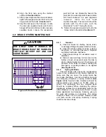
The brake assemblies should be inspected and
adjusted every 2,000 miles or monthly. Examine
the brake linings visually to locate the lining show-
ing the greatest amount of wear. The wheel and
drum should be removed and the linings replaced
if the thinnest portion of the lining is 3/8 in. (9.5
mm) or less. Do not allow the linings to wear thin
enough that the lining rivet contacts the drum.
(See
Figure 4-11)
.
WARNING
DO NOT ALLOW GREASE TO CON-
TACT BRAKE LININGS AS THIS
COULD RESULT IN REDUCED BRAK-
ING PERFORMANCE.
a. Brake Adjustment
: This trailer is equipped
with automatic slack adjusters which compen-
sate for brake lining wear and keep brakes
adjusted. Brakes should not be adjusted
manually except when relining brakes.
b. Disassembly for 12-1/4" X 7-1/2" Brakes
(See Figure 4-12)
1.
Release brakes and back off slack
adjuster.
2.
Remove slack adjuster lock ring and slack
adjuster.
3.
Remove drum assembly
(See Figure
.
4.
Remove anchor pin retainers, washers,
and bushings.
5.
Remove anchor pins and brake shoes.
6.
Remove brake return springs.
7.
Remove camshaft lock ring, spacer washer
and camshaft.
8.
Remove roller pin retainers.
9.
Remove roller pins and rollers from shoes.
10.
Remove camshaft bushings and seals from
spider.
11.
After removing the shoes, completely
inspect all brake components, servicing
as necessary.
c. Reassembly for 12-1/4" X 7-1/2" Brakes
1.
Install new camshaft bushing and seals
into the spider.
IMPORTANT
WHEN INSTALLING CAMSHAFT SEALS, THE
SEAL ON THE SLACK ADJUSTER SIDE IS IN-
STALLED FACING INTO SPIDER. THIS AL-
LOWS GREASE TO PURGE OUTSIDE THE
BRAKE ASSEMBLY WHEN GREASING THE
CAMSHAFT BUSHING.
2.
Install cam roller assemblies onto the brake
shoes.
3.
Install “D” shaped camshaft washer onto
the camshaft.
4.
Install the camshaft into the spider. Install
spacer washer and lock ring retainer on
camshaft before sliding the camshaft
through the camshaft support bracket.
Install the slack adjuster, washer and lock
ring retainer.
5.
Install shoes, anchor pin bushings, anchor
pins, and spacers onto spider. Install
anchor lock rings.
IMPORTANT
ALWAYS USE ALL NEW SPRINGS WHEN
SERVICING BRAKES.
6.
Install brake return spring.
7.
Connect slack adjuster to brake chamber
pushrod.
8.
Adjust automatic slack adjuster as outlined
in Section
4-9.6 c.
4-15
Figure 4-11 Brake Lining Wear
Содержание 336C
Страница 3: ...MODEL 336C CAR CARRIER OPERATOR S MANUAL PURCHASED FROM DATE ADDRESS PHONE NO SERIAL NO...
Страница 8: ......
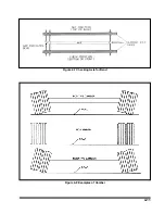
Страница 24: ...3 12 Figure 3 7 Lining Up the Over the Cab Deck Figure 3 8 Loading the Over the Cab Deck...
Страница 28: ...3 16 Figure 3 11 Loading the Lower Deck...
Страница 32: ...3 20 Figure 3 13 Rear Impact Guard and Antilock Brake System...
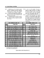
Страница 40: ...4 6 Figure 4 3 336C Wiring Diagram...
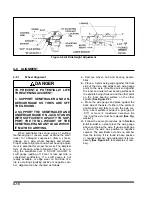
Страница 45: ...4 11 Figure 4 7 Checking Axle for Bend Figure 4 8 Examples of Camber...
Страница 50: ...4 16 Figure 4 12 Axle and Brake Assembly...
Страница 54: ...4 20 Figure 4 14 Outboard Mount Hub and Drum Figure 4 15 Inboard Mount Hub and Drum...
Страница 59: ...4 25 Figure 4 19 Mounting Tires and Wheels Figure 4 20 Stud Tightening Sequence...
Страница 70: ...NOTES 5 10...


