ULTRAHEAT
®
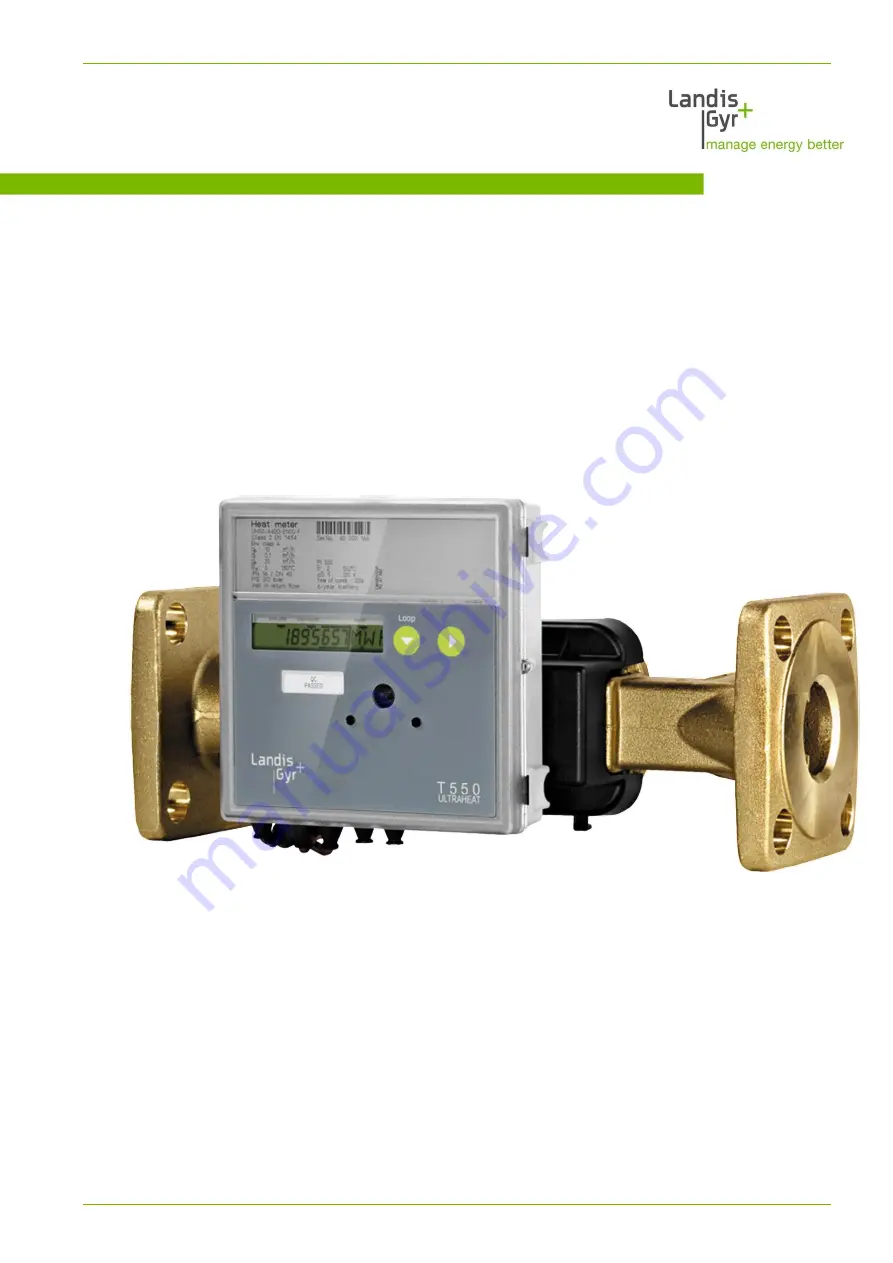
T550
(UH50…)
ULTRACOLD
Flow sensor T550
Technical description
32 16 101 001 h
Date: 23.08.2018
Gyr GmbH
Ultrasonic heating and cooling meter T550
Residential, district heating, local heating plant
Страница 1: ...0 UH50 ULTRACOLD T550 UH50 Flow sensor T550 UH50 Technical description 32 16 101 001 h Date 23 08 2018 Landis Gyr GmbH Ultrasonic heating and cooling meter T550 UH50 Residential district heating local heating plant ...
Страница 2: ...ding to EN1434 2014 1 1 000 total range Power measurement with maximum values tariffs selectable Data logger for system monitoring 60 monthly values Logbook Battery or mains operated Optical interface according to EN 62056 21 2003 Big range of communication modules for remote readout and system integration 2 module slots for using 2 communication modules coincidental Also operable as a flow meter ...
Страница 3: ...______19 Service loop 2 LOOP 2 ___________________________________________________19 Service loop 3 LOOP 3 __________________________________________________20 Service loop 4 LOOP 4 __________________________________________________21 6 2 Previous year s values __________________________________________________ 22 6 3 Monthly values ________________________________________________________ 22 7 Res...
Страница 4: ...CD ______________________________________ 35 11 Error messages__________________________________________________________37 12 Log functions ___________________________________________________________38 13 Data logger optional _____________________________________________________40 14 Additional options _______________________________________________________41 15 Order codes type number key _______...
Страница 5: ...consumption from the volume and temperature difference The meter combines modern microcomputer technol ogy with innovative ultrasonic measurement technology for which no mechani cally moving parts are necessary This technology is thus wear free robust and largely maintenance free High precision and long term stability guarantee precise and accounts of charges Other available documentations Operati...
Страница 6: ...the electronic unit Be aware of sharp points on the thread flange and meas uring tube Only personnel trained in the installation and operation of meters in heating and cooling systems may install and remove the meter Only install or remove the meter when the pipes are pres sure less After installing the meter check the leak tightness of the system Guarantee and calibration validity will lapse if t...
Страница 7: ...not dispose of the meter and the batteries with domestic waste Observe the local stipulations and laws on disposal You can return the lithium batteries to the manufacturer for appropriate disposal following use When shipping please observe legal regulations in particular those governing the labelling and packaging of hazardous goods Do not open the batteries Do not bring batteries into con tact wi...
Страница 8: ...reshold f T 0 2 K Temperature difference T 3 K 120 K Temperature measurement range 0 180 C LCD 7 digit Optical interface Standard EN 62056 21 Communication Optional e g M Bus Separability Always optional cable length Temperature sensor Type Pt 500 or Pt 100 According to EN 60751 Temperature range 0 150 C up to 45 mm overall length 0 180 C from 100 mm overall length Volume measurement unit Protecti...
Страница 9: ... 3 15 6 160 3 8 1 2 3 2 5 130 G1 5 25 10 200 5 6 1 8 1 5 2 5 190 G1 5 25 10 210 5 3 1 7 1 5 2 5 190 DN20 5 25 10 210 5 3 1 7 3 3 5 260 G 1 1 4 7 35 14 60 14 4 5 3 3 5 260 DN25 7 35 14 60 14 4 5 5 6 150 G 1 1 4 12 60 24 240 12 3 9 3 6 260 G 1 1 4 12 60 24 180 14 4 5 3 6 260 DN25 12 60 24 180 14 4 5 5 10 200 G2 20 100 40 130 28 8 8 2 6 10 300 G2 20 100 40 110 30 9 5 4 10 300 DN40 20 100 40 130 28 8 ...
Страница 10: ...b c m h bar mm mm mm UH50 x03 0 6 16 130 G1 58 UH50 x04 0 6 25 130 G1 58 UH50 x05 0 6 16 110 G 48 UH50 x06 0 6 25 110 G 48 UH50 x07 0 6 16 190 G1 88 UH50 x09 0 6 25 190 G1 88 UH50 x21 1 5 16 110 G 48 UH50 x22 1 5 25 110 G 48 UH50 x23 1 5 16 190 G 1 88 UH50 x25 1 5 25 190 G1 88 UH50 x26 1 5 16 130 G1 58 UH50 x27 1 5 25 130 G1 58 UH50 x36 2 5 16 130 G1 58 UH50 x37 2 5 25 130 G1 58 UH50 x38 2 5 16 19...
Страница 11: ...ters with thread Fig 5 Overview dimensions of large meters with thread Order No qp PN a b c m h bar mm mm UH50 x45 3 5 16 260 59 G 1 B UH50 x47 3 5 25 260 59 G 1 B UH50 x50 6 16 260 59 G 1 B UH50 x60 10 16 300 59 G 2 B UH50 x63 10 16 200 59 G 2 B Fig 6 Overview dimensions of large meters qp 6 with tread short face to face length Order No qp m h PN bar c m h bar UH50 x55 6 16 G 1 B Alternative moun...
Страница 12: ...50 x65 15 25 50 270 59 155 125 18 4 102 20 UH50 x69 15 25 50 200 59 155 125 18 4 102 20 UH50 x70 25 25 65 300 52 185 145 18 8 122 22 UH50 x74 40 25 80 300 56 200 160 18 8 138 24 UH50 x82 60 16 100 360 68 235 180 18 8 158 24 UH50 x83 60 25 100 360 68 235 190 22 8 158 24 Large meter qp 150 Fig 8 Overview all dimensions of large meter qp 150 Order No qp PN DN a b Øc Ød Øe No of holes f g m h bar mm m...
Страница 13: ... circuit as the meter Observe the admixtures Seal the temperature sensors and the fittings to protect against manipula tion Loosen the elastic band or the cable tie provided for the transport from the volume measurement unit In operation the temperature sensor and the control cable should not depend directly on the volume measurement unit If you install the meter for cooling metering follow the ap...
Страница 14: ...es for sensor adapter set temperature sensor directly immersed A mounting set is included for meters with 5 2 45 mm temperature sensors It allows for mounting the temperature sensors directly immersed into an insert or a ball valve for example 1 Install with the O ring at the point of installation with the fit up aid pen pro vided 2 Place both halves of the plastic bolting round the 3 notches of t...
Страница 15: ...he wall Make a loop downwards in order to prevent condensation running along the connected lines into the electronic unit Transducer cover Fig 14 Recommended installation position for cooling metering 4 2 Installation of qp 150 Note Use flange bolts with a length of at least 100 mm to install the flanged body in the pipeline As an assembly aid 2 M10 threads are mounted on the flange The threads al...
Страница 16: ...Dimension of electronic unit 16 49 5 Dimension of electronic unit Fig 15 Dimensions of electronic unit Fig 16 Plan view and cross section of adapter plate ...
Страница 17: ...e button To call up the pa rameterization op eration of the me ter Accessible after removing the cover 2 Button 2 Switches to the next display value within a loop 3 Button 1 Switches to the next loop 4 Optical interface Permits data com munication via a computer with the necessary service software 1 2 3 4 ...
Страница 18: ...th display range and data displayed can differ from the description depending on the appliance parameterization Certain button functions can also be blocked Display values LOOPs User loop Service loop 1 Service loop 2 User loop After the last loop is displayed the user loop LOOP 0 comes up again User loop LOOP 0 The LCD shows the following values one after the other Energy accumulated with tariff ...
Страница 19: ...rent temperature cold side in 2 sec cycles Operating time Operating time with flow Missing time Property number 8 digit Date Yearly set day DD MM Energy previous year on set day Volume previous year on set day Firmware version Service loop 2 LOOP 2 Service loop 2 displays the measurement period for establishing the maxi mum The LCD displays the following values one after the other Head of the loop...
Страница 20: ...w on the set day in 2 sec cycles with date stamp Max power on the set day in 2 sec cycles with date stamp Max temperatures on the set day in 2 sec cycles with date stamp MV for hot side or MR for cold side Missing time count on the set day After the last display the previously selected set day is displayed once again Note If the number of months to be read out is changed with the service software ...
Страница 21: ... the loop Current tariff in 2 sec cycles with threshold value 1 Measurement interval flow Measurement interval temperature Module 1 M Bus module M Bus primary address 1 M Bus secondary address 8 digit Module 2 Pulse module channel 1 energy channel 2 volume in 2 sec cycles Value for energy pulses Value for volume pulses Pulse duration in in ms for fast pulse ...
Страница 22: ...old side 6 3 Monthly values The meter stores the following values for 60 months on the monthly set day Energy meter status Volume meter status Tariff register meter status Missing time meter status Flow measurement time meter status and the maxima with date stamp for Flow Power Temperature difference Temperature hot side Temperature cold side The monthly values can be read via the optical and the ...
Страница 23: ...Resolution of the display 23 49 7 Resolution of the display Note The number of places after the decimal point of a value is based on the chosen measurement path and the chosen dimension ...
Страница 24: ...ally whether it is being powered from a battery or power supply Power supply requirements Requirements for measuring timebase Q 4 s and time base T 30 s 6 years 11 years 16 years Power supply 230 110 V AC 24 V ACDC Standard pulses M Bus read out max each 15 min CL Module 2x AA C D yes Radio module 868 MHz mo bile radio 16 sec transmis sion interval D D yes Radio module 868 MHz sta tionary radio 15...
Страница 25: ... Voltage 85 121 V AC or 196 253 V AC Type Safety class II Frequency 50 60 Hz Line voltage fluctuations maximal 10 of the nom voltage Overvoltage category II per EN60010 2500 V pulse voltage Power consumption maximal 0 8 VA Relative humidity less than 93 for T 50 C Fuse protection 6 A MCB 100 240 V alternating voltage Voltage 100 240 V AC 10 Type Safety class II Frequency 50 60 Hz Line voltage fluc...
Страница 26: ...f the following communication modules Pulse module CL module M Bus module G2 M Bus module G4 M Bus module G4 MI with 2 pulse inputs Analog module Radio module 868 MHz GPRS module These modules do not have an effect on the measurement You can retrofit the modules at any time without damaging the security seal Note You will find the technical details and data on communica tion modules in their respe...
Страница 27: ... yes yes MB MI yes yes yes yes yes yes 1 no yes yes CL yes yes yes yes 1 yes 1 no yes yes yes Restrictions only 1 module with fast pulses is possible only permissible on slot 2 min pulse duration 2 ms if pulse module 1 not fitted 5 ms if pulse module 1 fitted Subsequent mounting of a further pulse module in module slot 1 can result in changed output values for module 2 1 For M bus with fast read o...
Страница 28: ...permits the output of pulses that can be derived from the quantity of heat the volume tariff register 1 tariff register 2 or the mistake sta tus Two channels are available whose functions can be parameterized with the service software Output takes the form of standard pulses or fast pulses The pulse duration is identical for channel 1 and channel 2 Labeling pulse module Display in LCD CE C2 CV CT ...
Страница 29: ... description TKB 3436 9 3 M Bus module G4 The M Bus module enables the meter to communicate with an M Bus center in order to transmit measured values Standard EN 1434 3 EN 13757 2 3 Protocol EN 60870 5 Electrical isolation from the meter yes from the pulse inputs no Connection Strip back length 5 mm Connection capacity rigid or flexible 0 25 0 75 mm flexible with wire end ferrule 0 25 0 75 mm Pola...
Страница 30: ... TKB3448 Pulse Number of pulse inputs 2 pulse inputs per MI module Life of the module battery 5 years of operation 1 year storage duration if the M bus voltage is applied for at least 90 of the operating time the battery life increased to 10 years Standard for pulse inputs Class IB per EN 1434 2 Frequency Max 10 Hz Pulse duration low 50 ms No pulse duration high 50 ms Pulse value 0 01 liters pulse...
Страница 31: ...availed C1 mode OMS 4 1 2 with security profile B The radio module 868 MHz enables the meter to communicate with a center receiver using 868 MHz radio frequency The module supports OMS1 compliant data transmission with radio mode T1 or C1 and with or without en cryption see chapter 16 17 A data transmission to an OMS radio concentrator Smart Meter Gateway or the L G mobile radio readout system Q4 ...
Страница 32: ...attery for 16 years via power supply 110 230 24 V not with Elvaco 24V Standard LoRaWAN Version 1 0 Class A bi directional Long Range Wide Area Network LoRaWAN is a low power wireless network pro tocol The LoRaWAN specification is defined by LoRa Alliance is freely available and uses a special modulation technique Depending on the structure of the building can deviate significantly If the battery o...
Страница 33: ...D Indication green yellow red M Bus standard 13757 M Bus Baud rate 300 and 2400 Bit sec Transparent M Bus Listening server on TCP and GSM data Maximum connected M Bus slaves 8 Maximum cable length 1000 m Real Time Clock Backup 3 days Real Time Clock Accuracy 2 sec day Data storage Data logger function 1 3 MByte SIM card is required Communication protocols E Mail using SMTP with authentication mode...
Страница 34: ...ter Summation in the relevant tariff register is only performed if the relevant threshold is exceeded Threshold 1 exceeded Summation in tariff register 1 Thresholds 1 and 2 exceeded Summation in tariff register 2 Thresholds 1 2 and 3 exceeded Summation in tariff register 3 Supplied quantity of energy tariff T7 In tariff register 1 a quantity of energy is summated that is calculated from the temper...
Страница 35: ...elevant M bus command one of the 3 tariffs can be acti vated or all tariffs can be deactivated Surcharge quantity tariff by means of return temperature tariff T12 The quantity of energy is summated depending on the temperature cold side in tariff registers 1 or 2 The summated quantity of energy is calculated from the difference of the tem perature cold side from the defined return temperature thre...
Страница 36: ... 2 sec cycles for T10 switching times in 2 sec cycles for T11 for T12 The contents of the tariff registers are displayed in the user loop after the quantity of energy For tariffs T2 T3 T4 T5 T6 T10 T11 and T12 tariff register 1 tariff register 2 tariff register 3 not for T12 for tariff T7 for tariff T8 for tariff T9 ...
Страница 37: ...re sensor Check cold side temperature sen sors replace if necessary F3 Electronics for temperature evaluation defective Exchange the meter F4 Problem with the power supply Battery flat Check connection Change battery F5 Short circuit hot side tem perature sensor Check hot side temperature sensors replace if necessary F6 Short circuit cold side tem perature sensor Check cold side temperature sen so...
Страница 38: ...onth and for the past 18 months without time stamp Ser No Description 1 F0 Air in measuring tube 2 F1 Interruption temperature sensor hot side 3 F2 Interruption temperature sensor cold side 4 F3 Error temperature electronics 5 F5 Short circuit temperature sensor hot side 6 F6 Short circuit temperature sensor cold side 7 F8 Temperature sensor error 8 hours 8 F9 ASIC error 9 Above max temperature in...
Страница 39: ...ions 39 49 20 Monthly set das parameterized 21 Master reset performed 22 All times deleted 23 Missing time deleted 24 Maxima deleted Note Read out is performed via the optical interface with the service software ...
Страница 40: ...suring period than 1 hour the largest value from the max imum values calculated within one hour applies Note Parameterization and read out are performed with the ser vice software Note Data transmission is in a manufacturer specific format Value set for data to be recorded Meter readings at the end of the period for Quantity of energy Tariff register 1 2 3 Volume Operating duration Fault duration ...
Страница 41: ...logger Heating meter for mounting place hot side Operable as flow meter Cooling meter 6 12 C Combined heat cold meter Length of the control cable between measurement tube and electronic unit up to 5 m Electronic unit for connecting temperature sensors in four wire technique ...
Страница 42: ... flowrate 1 5 m h length 190 mm nominal pressure PN16 connection G 1 B 23 Nominal flowrate 1 5 m h length 190 mm nominal pressure PN25 connection flanged DN 20 24 Nominal flowrate 1 5 m h length 190 mm nominal pressure PN25 connection G 1 B 25 Nominal flowrate 1 5 m h length 130 mm nominal pressure PN16 connection G 1 26 Nominal flowrate 1 5 m h length 130 mm nominal pressure PN25 connection G 1 2...
Страница 43: ...al plate for Montenegro Serbian ME Dial plate for Macedonia Macedonian MK Dial plate for Mongolia Mongolian MN Dial plate for The Netherlands Dutch NL Dial plate for Norway Norwegian NO Dial plate for Poland Polish PL Dial plate for Romania Romanian RO Dial plate for Serbia Serbian RS Dial plate for Russia Russian RU Dial plate for Sweden Swedish SE Dial plate for Slovak Republic Slovakian SK Dial...
Страница 44: ...c to national regulations CL Compliant to MID class 2 M2 Compliant to MID class 3 M3 Compliant with CEN 1434 class 2 T2 Compliant with CEN 1434 class 3 T3 Compliant acc to national regulations TL 13 Energy unit Code Display kWh until qp 10 A Display MWh with 3 decimal places as of qp 15 with 2 decimal places as of qp 150 with 1 decimal place B Display MJ until qp 2 5 C Display GJ with 3 decimal pl...
Страница 45: ...he information about lifetime of battery in chapter 8 Ordering example Order example OMS 2 9 1 P601 1 Protocol type 2 Sending interval 3 Encryption 4 Data telegram UH50 XYY0 Y 00 YXEX YYX 2 9 1 P601 E Radio module 868 MHz wireless M Bus 2 OMS v2 0 radio mode T1 0 Sending interval 12 seconds mobile radio 1 Security profile A encryption mode 5 AES 128 Bit for example to connect to receivers who not ...
Страница 46: ...he radio module retrieves data from the T550 calculator in a time grid of 15 minutes The transmission interval has a different parameterizable time grid The age of data indi cates the time difference between the transmission and the fetching of the data Ordering examples Order example OMS 7 0 3 P600 1 1 Protocol type 2 Sending interval 3 Encryption 4 Data telegram 5 Age of data UH50 XYY0 Y 00 YXQX...
Страница 47: ...5 15 G 6 150 G 1 1 4 190 14 F 6 260 G 1 1 4 DN25 140 16 H 10 200 300 G 2 DN40 130 28 I 10 300 G 2 110 30 J 15 270 DN50 110 45 K 15 200 DN50 95 49 L 25 300 DN65 105 77 M 40 300 DN80 160 100 N 60 360 DN100 115 177 O 150 500 DN150 120 433 P The indicated pressure loss of a flow sensor is at the nominal flowrate qp Using the Kv Factor which defines the flow rate at a pressure loss of 1 bar the pressur...
Страница 48: ...Pressure loss 48 49 Alternatively the value can be taken from the diagram 250 10 100 1000 0 1 1 10 100 pressure loss in mbar flow rate in m h 21 02 2017 A BC DE F G H I J K L M N O P ...
Страница 49: ...49 49 Landis Gyr GmbH Humboldtstrasse 64 90459 Nuremberg Germany www landisgyr eu ...