background image

Important Safety Information

2/10/21

1

Important Safety Information

Listed below are common practices that may or may not be applicable to the products 

described in this manual.

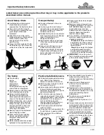
Tractor Shutdown & Storage

If engaged, disengage power 

take-off.

Park on solid, level ground and 

lower implement to ground or onto 

support blocks.

Put tractor in park or set park 

brake, turn off engine, and remove 

switch key to prevent unauthorized 

starting.

Relieve all hydraulic pressure to 

auxiliary hydraulic lines. 

Wait for all components to stop 

before leaving operator’s seat.

Use steps, grab-handles and 

anti-slip surfaces when stepping 

on and off the tractor.

Detach and store implement in an 

area where children normally do 

not play. Secure implement using 

blocks and supports.

OFF

REMOVE

Look for the Safety Alert Symbol

The SAFETY ALERT SYMBOL indicates there is a 

potential hazard to personal safety involved and extra 

safety precaution must be taken. When you see this 

symbol, be alert and carefully read the message that 

follows it. In addition to design and configuration of 

equipment, hazard control, and accident prevention are 

dependent upon the awareness, concern, prudence, and 

proper training of personnel involved in the operation, 

transport, maintenance, and storage of equipment.

Safety Precautions for 

Children

Tragedy can occur if the operator 

is not alert to the presence of 

children, Children generally are 

attracted to implements and their 

work.

Never assume children will remain 

where you last saw them.

Keep children out of the work area 

and under the watchful eye of a 

responsible adult.

Be alert and shut the implement 

and tractor down if children enter 

the work area.

Never carry children on the tractor 

or implement. There is not a safe 

place for them to ride. They may 

fall off and be run over or interfere 

with the control of the power 

machine.

Never allow children to operate the 

power machine, even under adult 

supervision.

Never allow children to play on the 

power machine or implement.

Use extra caution when backing 

up. Before the tractor starts to 

move, look down and behind to 

make sure the area is clear.

Safety at All Times

Careful operation is you best 

assurance against an accident. 
All operators, no matter how much 

experience they may have, should 

carefully read this manual and 

other related manuals, or have the 

manuals read to them, before 

operating the power machine and 

this implement. 

Thoroughly read and understand 

the “Safety Label” section. Read 

all instructions noted on them.

Do not operate the equipment 

while under the influence of drugs 

or alcohol as they impair the ability 

to safely and properly operate the 

equipment.

The operator should be familiar 

with all functions of the tractor and 

attached implement, and be able 

to handle emergencies quickly.

Make sure all guards and shields 

appropriate for the operation are in 

place and secured before 

operating the implement.

Keep all bystanders away from 

equipment and work area. 

Start tractor from the driver’s seat 

with hydraulic controls in neutral.

Operate tractor and controls from 

the driver’s seat only.

Never dismount from a moving 

tractor or leave tractor unattended 

with engine running.

Do not allow anyone to stand 

between tractor and implement 

while backing up to implement.

Keep hands, feet, and clothing 

away from power-driven parts.

While transporting and operating 

equipment, watch out for objects 

overhead and along side such as 

fences, trees, buildings, wires, etc. 

Do not turn tractor so tight as to 

cause hitched implement to ride 

up on the tractor’s rear wheel.

Store implement in an area where 

children normally do not play. 

When needed, secure implement 

against falling with support blocks.

!

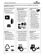
Be Aware of 

Signal Words

A signal word designates a degree or 

level of hazard seriousness. The 

signal words are:

Indicates a hazardous situation that, if 

not avoided, will result in death or 

serious injury. 

Indicates a hazardous situation that, if 

not avoided, could result in death or 

serious injury.

Indicates a hazardous situation that, if 

not avoided, may result in minor or 

moderate injury.

WARNING

CAUTION

!

!

DANGER

!

Содержание WC1504

Страница 1: ...d Decal Kit in French Language please see your Land Pride dealer Read the Operator s Manual entirely When you see this symbol the subsequent instructions and warnings are serious follow without exception Your life and the lives of others depend on it 35677 Wood Chipper WC1504 328 098M Operator s Manual Printed 2 10 21 ...

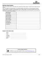
Страница 2: ...he weights and measurements are no longer accurate for your machine Update the record by adding the machine weight and measurements provided in the Specifications Capacities Section of this manual with the Option s weight and measurements Dealer Contact Information Model Number Serial Number Machine Height Machine Length Machine Width Machine Weight Delivery Date First Operation Accessories Name S...

Страница 3: ...nsions 13 Discharge Chute 14 Feed Chute 14 Inspect Twig Breaker Bar 14 Hitch Pin Set up 15 Driveline Installation 15 Tractor Shutdown Procedure 15 Tractor Hook up 16 3 Point Hook up 16 Quick Hitch Hook up 16 Leveling the Wood Chipper 16 Driveline Hook up 17 Check Driveline Collapsible Length 18 Check Driveline Maximum Length 19 Check Driveline Interference 19 Section 2 Operating Instructions 20 St...

Страница 4: ...the appropriate App on your smart phone open the App point your phone on the QR code and take a picture Dealer QR Locator The QR code to the left will link you to available dealers for Land Pride products Refer to Parts Manual QR Locator on this page for detailed instructions WC1504 Wood Chipper 328 098M Table of Contents See previous page for Table of Contents ...

Страница 5: ...ldren to play on the power machine or implement Use extra caution when backing up Before the tractor starts to move look down and behind to make sure the area is clear Safety at All Times Careful operation is you best assurance against an accident All operators no matter how much experience they may have should carefully read this manual and other related manuals or have the manuals read to them b...

Страница 6: ... Remove all tools and unused parts from equipment before operation Do not weld or torch on galvanized metal as it will release toxic fumes Tire Safety Tire changing can be dangerous and must be performed by trained personnel using the correct tools and equipment Always properly match the wheel size to the properly sized tire Always maintain correct tire pressure Do not inflate tires above recommen...

Страница 7: ...with the control of the power machine Riders can be struck by objects or thrown from the equipment Never use tractor or implement to lift or transport riders Prepare for Emergencies Be prepared if a fire starts Keep a first aid kit and fire extinguisher handy Keep emergency numbers for doctor ambulance hospital and fire department near the phone 911 Use Safety Lights and Devices Slow moving tracto...

Страница 8: ...e silica particles This dust can cause serious injury to the lungs silicosis There are guidelines which should be followed if crystalline silica quartz is present in the dust Be aware of and follow OSHA or other local State or Federal guidelines for exposure to airborne crystalline silica Know the work operations where exposure to crystalline silica may occur Participate in air monitoring or train...

Страница 9: ...Important Safety Information 2 10 21 5 This page left blank intentionally ...

Страница 10: ...locator at www landpride com 3 Some new equipment installed during repair requires safety labels to be affixed to the replaced component as specified by Land Pride When ordering new components make sure the correct safety labels are included in the request 4 Refer to this section for proper label placement To install new labels a Clean surface area where label is to be placed b Spray soapy water o...

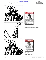
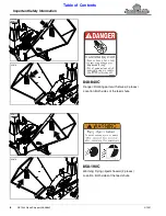
Страница 11: ...Important Safety Information Table of Contents WC1504 Wood Chipper 328 098M 2 10 21 7 818 132C Danger Thrown object hazard 2 places 848 840C Danger Rotating knives 35677 35679 35677 ...

Страница 12: ...ents WC1504 Wood Chipper 328 098M 2 10 21 8 848 840C Danger Rotating parts with knives 2 places Location Both sides of the feed chute 35677 35679 35677 35679 858 190C Warning Flying objects hazard 2 places Location Both sides of the feed chute ...

Страница 13: ... Warning Sharp object hazard 35677 35679 35679 35679 818 522C Danger Moving parts hazard 818 205C Rev B To prevent serious injury or death from moving parts Do not operate with guard missing Close secure drive guard before starting MOVING PARTS HAZARD WARNING 818 205C Warning Moving parts hazard ...

Страница 14: ...Important Safety Information Table of Contents WC1504 Wood Chipper 328 098M 2 10 21 10 35677 35678 35680 848 088C Danger Guard missing 3 Places 818 798C Warning Pinch point hazard ...

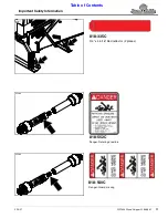
Страница 15: ...ant Safety Information Table of Contents WC1504 Wood Chipper 328 098M 2 10 21 11 35677 35294 35294 818 552C Danger Rotating driveline 818 540C Danger Guard missing 818 335C 3 4 x 4 5 16 Red reflector 2 places ...

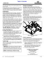
Страница 16: ...will help you get years of satisfactory use from this machine Application The Land Pride WC1504 Wood Chipper is designed and built by Land Pride to reduce unwanted tree limbs into useful landscape mulch typically found in flower beds gardens or just about anything you want to help retain moisture or just to aid in decomposition It has uses and applications in farming ranching nurseries campuses es...

Страница 17: ...Assembly Checklist Check Ref Make sure miscellaneous assembly tools are on hand Assortment of wrenches sockets Have a minimum of two people available during assembly Check to see if ballast weights are needed See specifications for weight of Wood Chipper Page 35 Make sure all major components driveline and loose parts are shipped with the machine Refer to section on Assembly and Set up Pages 13 19...

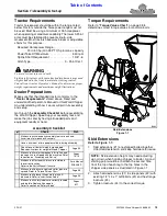
Страница 18: ...nug and then back each one off 1 2 turn 35681 NOTE Half clamp plate 7 and half spacer plate 5 are shipped bolted to discharge spout 1 IMPORTANT Be careful not to damage plastic surface attached to underside of discharge chute while attaching chute to the chipper s notched plate 4 Feed Chute Assembly Figure 1 3 Feed Chute Refer to Figure 1 3 WARNING To avoid serious injury or death Keep yourself an...

Страница 19: ...up 2 Remove shaft protector 10 from rotor shaft 1 3 On shear bolt end of driveline 2 Push push pins A B in and hold while starting to slide universal joint onto rotor shaft 1 35682 Driveline Assembly Figure 1 5 4 After universal joint starts onto the rotor shaft release push pins and continue to slide universal joint on until push pin releases and universal joint locks in place Move driveline back...

Страница 20: ...our nearest Land Pride dealer to purchase a Quick Hitch NOTE Clevis pin 3 linchpins 4 and hairpin cotter 6 are supplied by customer 3 Attach lower lift arms to hitch pins 5 Secure hitch pins with customer supplied linchpins 4 4 Connect hitch hole in top center 3 Point link to upper clevis hitch with customer supplied 3 4 clevis pin 3 and customer supplied hairpin cotter 6 5 Ensure that the lower h...

Страница 21: ... does not interfere with the tractor drawbar at maximum depth If needed shut tractor off and move or remove drawbar to prevent driveline damage IMPORTANT The driveline must be lubricated before putting it into service Refer to Lubrication Points on page 33 IMPORTANT An additional driveline may be required if implement is attached to more than one tractor or if a Quick Hitch is used IMPORTANT Skid ...

Страница 22: ...nd when alternating between using a quick hitch and a standard 3 point hitch More than one driveline may be required to fit all applications IMPORTANT The power take off shaft and implement input shaft must be aligned and level with each other when checking driveline minimum length A driveline that is too long can damage tractor and implement Driveline Shortening Figure 1 8 Refer to Figure 1 8 7 I...

Страница 23: ... been removed for clarity Maximum Driveline Movement During Operation Figure 1 10 2 Slowly and carefully lower and raise the implement to ensure drawbar tires and other equipment on the tractor do not contact the implement s frame If there is an interference a Back implement over the support blocks and lower it onto the blocks b Shut tractor down before dismounting Refer to Tractor Shutdown Proced...

Страница 24: ...ondition to avoid injury or death from driveline entanglement and parts flying off the driveline Feed only wood products through the chipper Chipping products other than wood can damage the driveline and rotor cause back feed injuries and create a thrown object hazard resulting in serious injury or death Adjust discharge chute to direct material away from operator people animals equipment and buil...

Страница 25: ...ays be sure of your footing Walk never run Wear a respirator or filter mask to protect lungs and airway Keep long hair tucked in Do not wear jewelry loose fitting clothing clothing with pull strings or other articles that can become entangled in product fed into the chipper or rotating components Transporting WARNING To avoid serious injury or death When traveling on public roadways travel in such...

Страница 26: ...Deflector Chute Angle on page 25 for detailed instructions 7 With engine speed at a low idle engage power take off and then slowly increase engine speed to 540 rpm 8 Untangle product before inserting it into the feed chute Slowly slide one piece at a time into the feed chute toward the rotor knives 9 To protect oneself do not reach past the rubber skirt inside the feed chute Instead use a stick or...

Страница 27: ...r into the feed chute one at a time You should release your grip once the product starts to self feed Be careful not to reach past the rubber skirting in the feed chute When necessary you should use a stick or board to push on objects beyond the rubber skirting You will immediately begin to see a generous stream of chips being rapidly ejected out of the discharge chute to a predetermined location ...

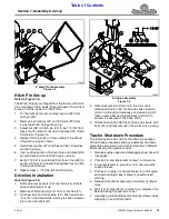
Страница 28: ...nder skid extensions 1 to keep chipper from drifting down while adjusting skid extensions 3 Lower Wood Chipper onto support blocks shut tractor engine off and remove switch key 4 Remove hex flange locknuts 3 and bolts 2 5 Lower skid extensions 1 to the ground and reinsert 1 2 13 GR5 cap screws 2 Secure cap screws with existing hex flange locknuts 3 Tighten locknuts to the correct torque 6 Raise tr...

Страница 29: ...an throw objects 1 Push down on rotation chute lock lever 1 and hold 2 Rotate discharge chute 2 in small increments until desired angle of discharge is achieved 3 Release lock lever 1 Make sure lever has locked into position and chute cannot rotate 35686 NOTE Chute is limited to 270o rotation so as not to get into loading area Adjust Deflector Chute Angle Figure 3 3 Deflector Chute Angle Refer to ...

Страница 30: ...s d Select the rotor knife 4 closest to the inside wall of rotor housing 13 and rotate that rotor knife to be in line with ledger knife 5 Check Ledger Knife Clearance CAUTION To avoid minor or moderate injury Knives and ledgers are sharp ALWAYS wear gloves and eye protection while inspecting and adjusting ledger clearance Refer to Figure 3 4 The knives 4 cut best if knife ledger 5 is adjusted with...

Страница 31: ... 9 Draw locknuts up snug and then back off one half turn 10 Secure feed chute 7 with two 1 2 13 hex whiz nuts 6 Tighten hex whiz nuts to the correct torque 11 Connect driveline to the tractor power take off shaft Cut Away View of Rotor Ledger Knife and Rotor Knife Figure 3 5 Adjust Ledger Knife Refer to Figure 3 5 Figure 3 4 on page 26 See Check Ledger Knife Clearance on page 26 to determine if ga...

Страница 32: ...ns after using the unit for several hours and on a regular basis thereafter to ensure they are tight and secured Lubricate components on schedule Replace worn damaged or illegible safety labels by obtaining them from your Land Pride dealer DANGER To avoid serious injury or death Work only in areas that are well ventilated Never operate an engine in a closed area without venting the exhaust fumes E...

Страница 33: ...lled and ledger knife cannot be adjusted to the proper clearance then replaced rotor knives with new knives See Check Ledger Knife Clearance on page 26 for allowable clearance dimensions b Reattach new rotor knives to rotor 1 with 3 8 bolts 5 Continue with steps 6 8 below 6 Tighten rotor knife bolts 5 to 35 40 ft lbs See Additional Torque Values on page 38 for more information 7 Adjust ledger knif...

Страница 34: ...ure twig breaker bar is centered as much as possible on all four rotor fin slots 4 9 Tighten 1 2 13 GR8 bolts 2 to the correct torque Refer to Figure 4 7 on page 31 10 Rotate upper rotor housing 2 down and secure with existing 3 8 16 hex flange serrated screw 6 Tighten serrated screw to the correct torque 11 Reattach driveline to tractor power take off shaft 35695 Land Pride Breaker Bar Part No s ...

Страница 35: ...ting Refer to Tractor Shutdown Procedure on page 15 2 Disconnect driveline from tractor power take off shaft 3 Unplug feed chute discharge chute and rotor as follows Unplug Feed Chute 4 a Be sure to complete steps 1 2 on this page b Pull all material out of feed chute Make sure nothing is jammed between inlet opening and rotor at bottom of feed chute c Loosen product jammed at the bottom with a st...

Страница 36: ... knives or replace with new rotor knives 6 Check ledger knife Rotate ledger knife or replace ledger knife when required 7 Check twig breaker bar Replace breaker bar if it is bent broken worn thin or has structural cracks Land Pride Shear Bolt Part No Part No Part Description 165 000 507 CO BOLT NUT M10 x 60 CL 8 8 8 Inspect Wood Chipper for loose damaged or worn parts Adjust and tighten loose part...

Страница 37: ...One Type of Lubrication Multi purpose Grease Quantity As required 35679 35677 50 Hrs Multi purpose spray lube Multi purpose grease lube Multi purpose oil lube Intervals in hours at which lubrication is required Lubrication Legend Rear Flange Bearing Zerks One Type of Lubrication Multi purpose Grease Quantity As required 25 Hours 25 Hours ...

Страница 38: ...f outer shaft profile Type of lubrication Multi purpose Grease Quantity As required Driveline U Joints Zerks Two One on each end of driveline Type of lubrication Multi purpose grease Quantity of lubrication As required 80 Hours Shear Bolt Joint Zerks One on shear bolt end of driveline Type of lubrication Multi purpose grease Quantity As required 25 Hours 25 Hours ...

Страница 39: ...ive Rotor Size in cm 25 63 5 Chip Capacity in cm 4 10 2 Hopper Inlet Opening in cm 20 x 20 50 8 x 50 8 Chipper Inlet Opening in cm 10 x 4 25 4 x 10 2 Spout Discharge Opening in cm 5 1 4 13 3 Square Rotor Knife Reversible and Replaceable Number of Rotor Knives 4 Rotor Knife Size in cm 6 x 2 x 1 4 15 2 x 5 1 x 0 6 Rotor Knife Material Hardened Steel Specifically designed for chipping Feed System Sel...

Страница 40: ... are worn out 4 Bolt Flanged Bearings Improves bearing life Cat 4 Shear Bolt Driveline Shear bolt protects the unit when obstructions are encountered Skid Extension Supports Allows the unit to sit on the ground while keeping the driveline near level Extends life of driveline u joints Adjustable Rotating Discharge Chute With Rotation Stops Directs direction wood chips will be discharged Chute rotat...

Страница 41: ...ng See Plugged Chutes Rotor on page 31 Discharge chute is plugged Clean discharge chute See Plugged Chutes Rotor on page 31 Clearance between rotor knife and ledger knife is too large Readjust ledger See Check Ledger Knife Clearance on page 26 Ledger knife is dull worn Rotate ledger knife or replace ledger knife See Ledger Knife Maintenance on page 29 Rotor will not turn Driveline is not engaged E...

Страница 42: ...50 285 210 M16 X 1 5 155 115 240 180 335 245 5 8 18 150 110 230 170 325 240 M18 X 2 5 195 145 310 230 405 300 3 4 10 235 170 360 265 510 375 M18 X 1 5 220 165 350 260 485 355 3 4 16 260 190 405 295 570 420 M20 X 2 5 280 205 440 325 610 450 7 8 9 225 165 585 430 820 605 M20 X 1 5 310 230 650 480 900 665 7 8 14 250 185 640 475 905 670 M24 X 3 480 355 760 560 1050 780 1 8 340 250 875 645 1230 910 M24...

Страница 43: ... Misuse also specifically includes failure to properly maintain oil levels grease points and driveline shafts Claims under this Warranty should be made to the dealer which originally sold the product and all warranty adjustments must be made through an authorized Land Pride dealer Land Pride reserves the right to make changes in materials or design of the product at any time without notice This Wa...

Страница 44: ...Corporate Office P O Box 5060 Salina Kansas 67402 5060 USA www landpride com ...

Отзывы: