


Section 2: PFS4000 Assembly & Set-Up
PFS4000, PFS5060 & PFS8010 Pendulum Spreaders 309-124M
11/20/20
16
The following instructions are for the PFS4000 model.
See page 18 for PFS5060 and page 21 for PFS8010.
See page 14 for drive unit assembly instructions.
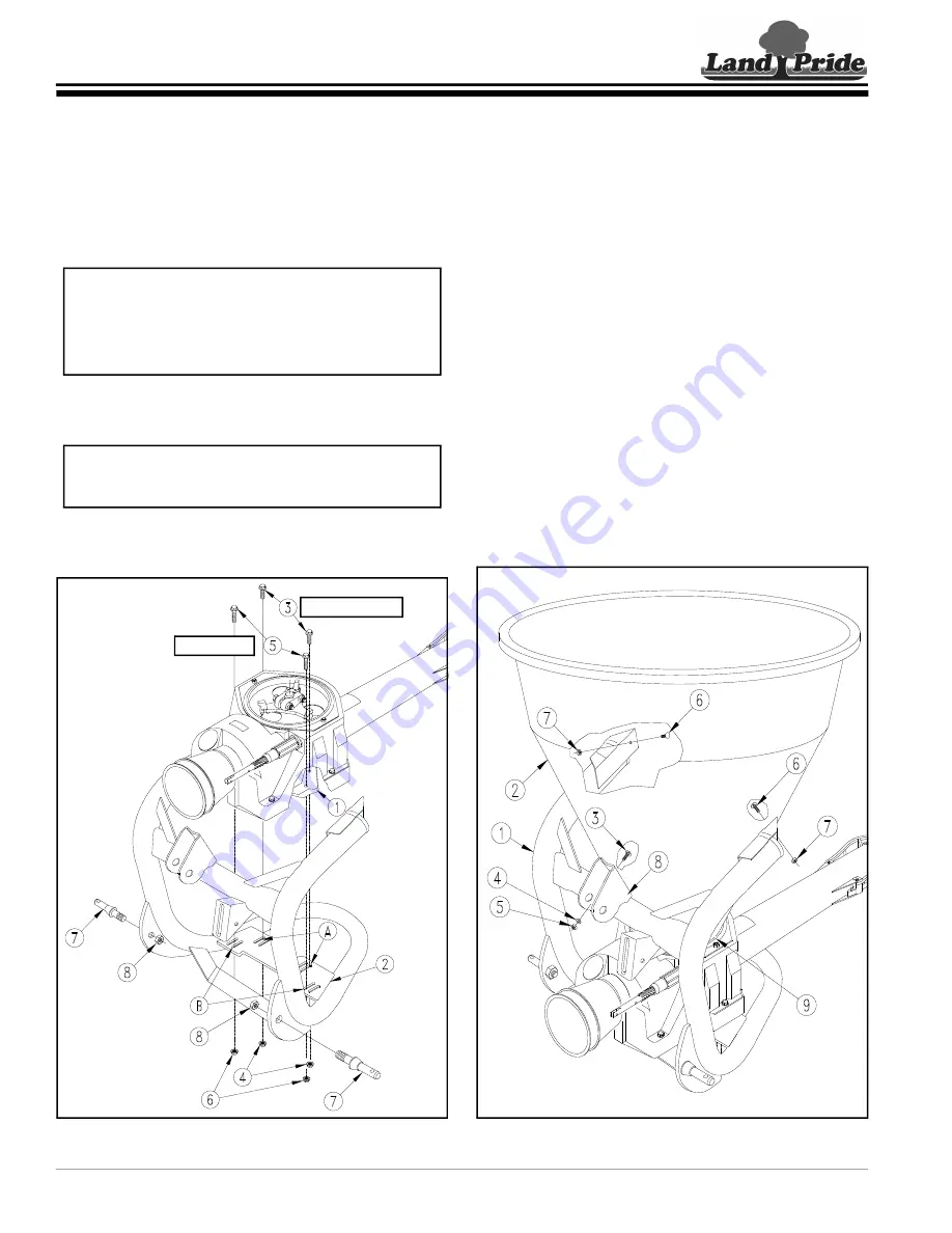
Drive Unit Assembly to Main Frame
Refer to Figure 2-1:
1. Attach hitch pins (#7) to the main frame with 3/4" hex
nuts (#8). Tighten nuts to the correct torque.
2. Insert M12 x 50 (2") bolts (#5) into front holes and
M12 x 40 (1 1/2") bolts (#3) into the back holes of
drive frame (#1).
3. Attach drive frame (#1) to inside slots “B” first and
outside slots “A” last in mounting plate (#2) with hex
nuts (#4 ). Do not tighten hex nuts at this time.
Drive Unit Assembly
Figure 2-1
IMPORTANT:
Drive Unit assembly is heavy and
requires 2 people to safely install to the main frame.
Do not tighten nuts (#4 & #6) until after hopper is
installed. This will allow for proper alignment of
hopper to drive unit assembly.
NOTE:
If rear bolts (#3) are difficult to install into
slots “A” in mounting plate (#2), pivot rear of drive
unit up and down to insert bolts through slots “A”.
30759
2" Lg. Bolts
1 1/2" Lg. Bolts
Hopper Assembly
Refer to Figure 2-2:
1. Rotate hopper until mounting holes in hopper are in
alignment with main frame mounting holes (Land
Pride Logo will be to the back).
2. Lower hopper (#2) onto main frame (#1) until
centered and resting above drive unit flange (#9).
3. Attach hopper sides first to the main frame with
M10 x 30 (1 3/16") round head screws (#6) and hex
nuts (#7). Draw nuts up snug, do not tighten at this
time.
4. Adjust drive unit forward or rearward until hole in the
front of the hopper mates with hole in the 3-point
clevis bracket (#8) and hopper bottom is centered
over the drive unit flange (#9).
5. Attach hopper front to 3-point clevis bracket (#8) with
M10 x 30 (1 3/16") round head screw (#3), flat washer
(#4) and hex nut (#5) as shown.
6. Tighten hopper mounting nuts (#5 & #7) to the
correct torque.
7.
Refer to
Make final adjust to the position
of the drive unit and tighten hex nuts (#4 & #6) to the
correct torque.
Hopper Assembly
Figure 2-2
30760
Section 2: PFS4000 Assembly & Set-Up


