lancer UNICORN TOWER Скачать руководство пользователя страница 15

15

General Information

CLEANING AND SANITIZING

• 

Lancer equipment (new or reconditioned) is shipped from the factory cleaned and sanitized in accordance with NSF guidelines. 

The operator of the equipment must provide continuous maintenance as required by this manual and/or state and local health 

department guidelines to ensure proper operation and sanitation requirements are maintained.


The cleaning procedures provided herein pertain to the Lancer equipment identified by this manual. If other


equipment is being cleaned, follow the guidelines established by the manufacturer for that equipment.

•  Use sanitary gloves when cleaning the unit and observe all applicable safety precautions.

•  DO NOT

 use a water jet to clean or sanitize the unit.

•  DO NOT

 disconnect water lines when cleaning and sanitizing syrup lines, to avoid contamination.

•  DO NOT

 use strong bleaches or detergents; These can discolor and corrode various materials.

•  DO NOT

 use metal scrapers, sharp objects, steel wool, scouring pads, abrasives, or solvents on the dispenser.

•  DO NOT

 use hot water above 140° F (60° C). This can damage the dispenser.

•  DO NOT

 spill sanitizing solution on any circuit boards. Insure all sanitizing solution is removed from the system.

NOTE

• 

Cleaning should be accomplished only by trained personnel. Sanitary gloves are to be used during cleaning operations.           

Applicable safety precautions must be observed. Instruction warnings on the product being used must be followed.

ATTENTION

Unplug the dispenser before servicing, cleaning, or 

sanitizing any of the equipment.

WARINING

Cleaning and Sanitizing Solutions

Cleaning Solution


Mix a mild, non-abrasive detergent (e.g. Sodium Laureth 

Sulfate, dish soap) with clean, potable water at a temperature 

of 90°F to 110°F (32°C to 43°C). The mixture ratio is one 

ounce of cleaner to two gallons of water. Prepare a minimum of 

five gallons of cleaning solution. Do not use abrasive cleaners 

or solvents because they can cause permanent damage to the 

unit. Ensure rinsing is thorough, using clean, potable water at a

temperature of 90°F to 110°F. Extended lengths of product lines 

may require additional cleaning solution.

Sanitizing Solution 

Prepare sanitizing solutions in accordance with the 

manufacturer’s written recommendations and safety guidelines.

The solution must provide 100 parts per million (PPM) chlorine

(e.g. Sodium Hypochlorite or bleach). A minimum of five

gallons of sanitizing solution should be prepared. Any sanitizing

solution may be used as long as it is prepared in accordance 

with the manufacturer’s written recommendations and safety 

guidelines, and provides 100 parts per million (PPM) chlorine.

Daily Cleaning

1.  Disconnect power to the unit.
2.  Mix an appropriate amount of cleaning solution in a clean 

container, then pour a small portion of the cleaning solution  

in separate clean container (at least 3 inches deep).

3.  Remove nozzle by twisting counterclockwise and pulling    

down.

4. 

Submerge the nozzle in the container with the smaller  


portion of solution.

5. 

Use a clean cloth soaked in the cleaning solution to  


clean the tower and all exterior stainless steel surfaces.

6.  Use the soaked cloth to wipe clean all splash areas.
7.  Rinse nozzle in warm water then re-install on tower. 
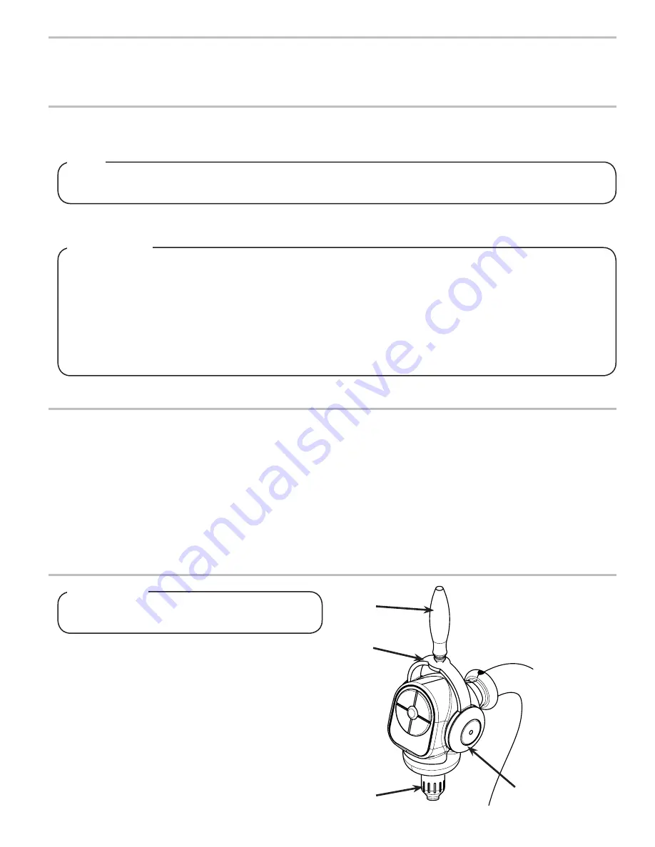
A

B

C

D

A. Ceramic Lever

B. Handle

C. Nozzle

D. Chrome Disk

Содержание UNICORN TOWER

Страница 1: ...k of Lancer 2021 by Lancer all rights reserved Lancer Worldwide 6655 Lancer Blvd San Antonio Texas 78219 800 729 1500 Technical Support Warranty 800 729 1550 custserv lancerworldwide com lancerworldwi...

Страница 2: ...e Adjustment 11 PROGRAMMING AND CONFIGURATION 12 13 Programming Overview 12 Valve Configuration 12 Purge Mode 13 Timed Pour Mode 13 Portion Control Programming 13 CLEANING AND SANITIZING 14 15 General...

Страница 3: ...dispenser from the power source to service the unit Only qualified personnel should service internal components of electrical control housing WARNING Make sure that all water lines are tight and units...

Страница 4: ...equired and a Secondary Voltage 24 VAC Overcurrent and surge protection is recommended PLAIN WATER SUPPLY Min Flowing Pressure 40 PSIG 0 276 MPA Max Pressure 110 PSIG 0 756 MPA SYRUP SUPPLY Min Pressu...

Страница 5: ...ry Voltage 24 VAC Overcurrent and surge protection is recommended PLAIN WATER SUPPLY Min Flowing Pressure 40 PSIG 0 276 MPA Max Pressure 110 PSIG 0 756 MPA SYRUP SUPPLY Min Pressure 20 PSI 0 137 MPA M...

Страница 6: ...rup Containers J Floor Drain A Water Source B CO2 Source C High Pressure CO2 Regulator D Electrical Outlet E Tower Dispenser F Junction Box G Recirculation Unit H Syrup Pump I BIB Syrup Container J Fl...

Страница 7: ...R DESCRIPTION 85 3151R 21 11111 00 TOWER UNICORN RECIRC TC PC CC VV R GI 85 3151R 21 11111 TOWER UNICORN RECIRC TC PC CC VV R 85 3151R 20 11111 22 TOWER UNICORN TC PC CC VV R AUS 85 3161R 21 11111 TOW...

Страница 8: ...cation where the unit is to be installed Verify the selected counter is strong enough to safely support the weight of the installed unit after the cutout for the unit is made The ideal counter for ins...

Страница 9: ...ition the tower facing forward with the nozzle above the drip tray Do not over tighten this can cause damage to the ceramic lever ATTENTION Do not over tighten this can cause damage to the ceramic lev...

Страница 10: ...inches of the Tower assembly See image below or Wiring Diagram located in Junction Box or on pages 27 and 28 of this manual for reference NOTE NOTE 1 Position the Mounting Bracket of the Junction Box...

Страница 11: ...ement NOTE NOTE Check the water filter periodically as required by local conditions It is the responsibility of the installer to ensure compliance ATTENTION 5 Route all syrup and water lines from the...

Страница 12: ...vel is even with the water level Use a screwdriver to adjust if needed 7 Repeat process for each syrup brand 8 Remove syrup separator and re install nozzle A A B B C C A Syrup Separator B Ratio Cup C...

Страница 13: ...onfiguration 1 On the main board in the junction box there is a SW1 switch that determines how the valves on the tower work Any changes to the SW1 switch will cause the dispenser to reset 2 Leave Togg...

Страница 14: ...wered on the Purge Mode can be accessed by pressing and holding both the Brand 1 and Brand 4 buttons for 5 seconds 2 During Purge Mode the Mode LED blinks at a low duty cycle 1 If unit is in Idle Mode...

Страница 15: ...e equipment WARINING Cleaning and Sanitizing Solutions Cleaning Solution Mix a mild non abrasive detergent e g Sodium Laureth Sulfate dish soap with clean potable water at a temperature of 90 F to 110...

Страница 16: ...ning solution gently clean the handle and ceramic lever 9 Re install the handle by aligning the set pins with the notches on both sides of the dispensing tower 10 Gently push the handle into place the...

Страница 17: ...e spool movement 5 Replace BIB pump Erratic ratio 1 Incoming water and or syrup supply not at minimum flowing pressure 2 Foreign debris in water and or syrup flow controls 3 Tolerance of parts afffect...

Страница 18: ...er see Insufficient Water Flow on previous page 2 Reset by turning the unit OFF and then ON Excessive foaming 1 Incoming water or syrup temperature too high 2 CO2 pressure too high 3 Water flow rate t...

Страница 19: ...r replace lines 5 Replace BIB pump BIB pump operated but no flow 1 Leak in syrup inlet or outlet line 2 Defective BIB pump check valve 1 Replace line 2 Replace BIB pump BIB pump continues to operate w...

Страница 20: ...m Part No Description 01 52 3732 Harness Main Controller Unicorn 02 52 3344 Harness LFCV Thru Central Valve Unicorn 03 52 3358 Harness Bypass Unicorn 04 64 5048 PCB Assembly Main Board Unicorn 05 05 1...

Страница 21: ...cription 01 52 3381 Harness Water Module VV Recirc Unicorn 02 52 3359 Harness Solenoid KIP VV Unicorn 03 52 3360 Harness Solenoids VV Unicorn 04 52 3358 Harness Bypass Unicorn 05 64 5048 02 PCB Assemb...

Страница 22: ...ank Plate Used only with Single Brand Unicorn Tower 85 3161R 12 2204 03 17 0647 01 Solenoid 24 VDC 1 8 NPT 2 WNC 04 05 2971 Elbow Quick Connect 1 4 x 1 8 05 05 1736 Body Plug Used only with Single Bra...

Страница 23: ...0999 04 01 2762 Fittingg Soda Outlet Unicorn 05 02 0005 O Ring 2 010 97 0999 06 02 0214 O Ring 2 008 97 0999 07 05 2929 Fitting Inlet Nozzle Syrup 08 04 1639 Screw 4 20X 250 IN PH Phillips Plastitie...

Страница 24: ...nector 3 8 S Fit X 3 8 S Fit 03 19 0267 02 Valve Assembly LFCV 2 0 Soda Gray S 04 05 1385 Elbow 5 Dole X 2 Barb Pls 05 02 0089 O Ring 2 012 97 0999 06 19 0266 02 Valve Assembly LFCV 2 0 Syrup Black SC...

Страница 25: ...2 012 97 0999 03 19 0399 Water Module Vol 1 5 3 0 04 05 0967 Retainer Sol Vlv Ball Vlv Premia 05 02 0005 O Ring 2 010 97 0999 06 05 1386 Elbow 375 Dole X 2 Barb PLS 07 19 0398 Syrup Module Vol 1 5 3...

Страница 26: ...01 64 5057 PCB Assembly Touch Pad Unicorn W Portion Control 02 01 2757 Fitting Wye 12I d Unicorn 03 01 2806 Jg Bulkhead Connector 3 8 S Fit X 3 8 S Fit 79000217 04 05 3475 Single Brand Blank Plate Us...

Страница 27: ...27 Wiring Diagram LFCV...

Страница 28: ...28 Wiring Diagram VV...

Страница 29: ...29 Counter Cutout Not to Scale...

Страница 30: ...Lancer Worldwide 800 729 1500 Technical Support Warranty 800 729 1550 custserv lancerworldwide com lancerworldwide com...

Отзывы: