LEGACY FG
033-0004
Page S.7
REV. 0/04-23-2007
Supplement–Legacy Fixed Gear
Lancair International Inc., Represented by Neico Aviation Inc., Copyright 2007 Redmond, OR 97756
7. Check the angle of the gear leg.
• Needs to be at approx. 50° from horizontal.
• And, needs to be within
0.5°.
8. Adjust the position of the upper-leg attachment on the
wing spar as needed to obtain the 50° angle and re-
clamp.
9. Recheck the angle of the gear leg and make any
necessary adjustments.
10. Back drill and install the screws that hold the upper-leg
attachment in place.
Countersink from the front and insert a screw
(MS24694-S154) in each hole.
Add a washer (AN960-516) to the back and secure
with a nut (AN365-528A).
Now you are ready to install the gear leg.
Attaching the Gear Leg
You may have temporarily inserted the gear leg into the
upper gear attachment in the previous section when you
checked the angle of the leg, now you will finish the
installation.
±
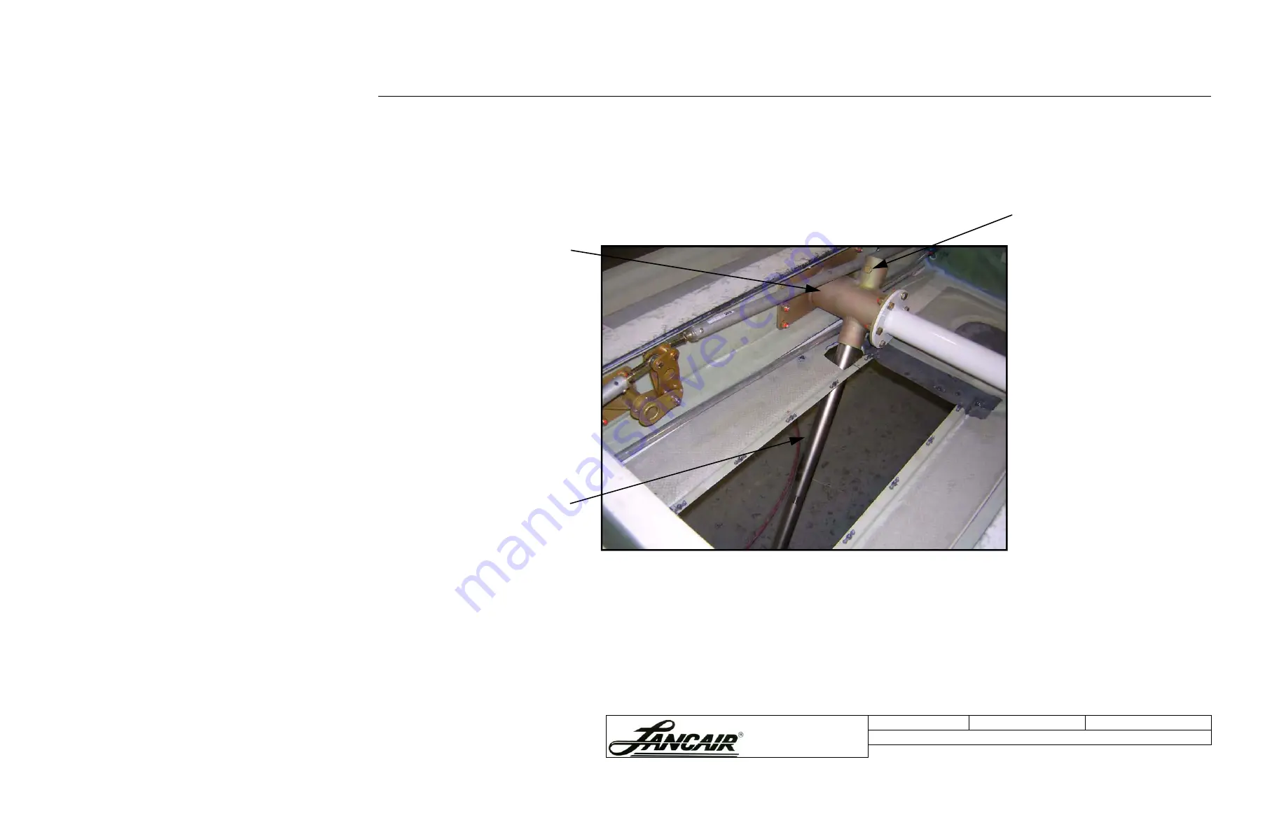
Figure S.4.B.2 Completed upper-leg attachment with gear leg
Upper-leg
attachment
Gear leg
Installing the Gear Leg
The gear leg is already inserted into
the upper gear attachment.
1. Insert a bolt (AN4-22A), from the
top, through the sleeve and the
gear leg.
2. Secure the bolt with a washer
(AN960-416) and a locknut
(AN365-428A).
5
0
D
E
G
.


