background image

MX SERIES 250 

WASTE OIL HEATER 

MX SERIES 300 

WASTE OIL HEATER 

Installation and Operating Instructions

Table of Contents:

Rules For Safe Installation and Operation   . . . . . . . . . . . . . . . . . . . . . . . . . . . . . . . . . . . page     2

Sec. 1

General Specifications and Hazards . . . . . . . . . . . . . . . . . . . . . . . . . . . . . . . . . . . . . . . . . . page     4

Sec. 2

Heater Installation . . . . . . . . . . . . . . . . . . . . . . . . . . . . . . . . . . . . . . . . . . . . . . . . . . . . . . . . . . . . . . page  10

Sec. 3

Chimney /Vent System  . . . . . . . . . . . . . . . . . . . . . . . . . . . . . . . . . . . . . . . . . . . . . . . . . . . . . . . . page  12

Sec. 4

Draft . . . . . . . . . . . . . . . . . . . . . . . . . . . . . . . . . . . . . . . . . . . . . . . . . . . . . . . . . . . . . . . . . . . . . . . . . . . . . page  15

Sec. 5

Fuel Supply Tank /Piping Installation  . . . . . . . . . . . . . . . . . . . . . . . . . . . . . . . . . . . . . . . . . page  15 

Sec. 6

Fuel Supply Pump/Piping  . . . . . . . . . . . . . . . . . . . . . . . . . . . . . . . . . . . . . . . . . . . . . . . . . . . . . page  17 

Sec. 7

Compressed Air Installation . . . . . . . . . . . . . . . . . . . . . . . . . . . . . . . . . . . . . . . . . . . . . . . . . . . page  19 

Sec. 8

Electrical Connections/Wiring Diagram . . . . . . . . . . . . . . . . . . . . . . . . . . . . . . . . . . . . . . page  20 

Sec. 9

Controls  . . . . . . . . . . . . . . . . . . . . . . . . . . . . . . . . . . . . . . . . . . . . . . . . . . . . . . . . . . . . . . . . . . . . . . . . . page  23 

Sec.10

Priming Fuel Pump  . . . . . . . . . . . . . . . . . . . . . . . . . . . . . . . . . . . . . . . . . . . . . . . . . . . . . . . . . . . . page  25 

Sec.11

Burner Start-Up Procedure . . . . . . . . . . . . . . . . . . . . . . . . . . . . . . . . . . . . . . . . . . . . . . . . . . . . page  27 

Sec.12

Flame Adjustment  . . . . . . . . . . . . . . . . . . . . . . . . . . . . . . . . . . . . . . . . . . . . . . . . . . . . . . . . . . . . . page  29 

Sec.13

Maintenance Schedule / Service Adjustments . . . . . . . . . . . . . . . . . . . . . . . . . . . . . . page  32 

Sec.14

Troubleshooting  . . . . . . . . . . . . . . . . . . . . . . . . . . . . . . . . . . . . . . . . . . . . . . . . . . . . . . . . . . . . . . . page  44 

Sec.15

Warranty Certificate . . . . . . . . . . . . . . . . . . . . . . . . . . . . . . . . . . . . . . . . . . . . . . . . . . . . . . . . . . . . page  49 

Sec.16

Burner Reference Diagram . . . . . . . . . . . . . . . . . . . . . . . . . . . . . . . . . . . . . . . . . . . . . . . . . . . . page  51 

Visit our website at: www.lanair.com 

3

Содержание MX SERIES 250

Страница 1: ...MX SERIES 250 MX SERIES 300 WASTE OIL HEATER InstallationandOperating Instructions Lanair ProductsLLC 4109 Capital Circle Janesville Wisconsin 53546 1 888 370 6531 www lanair com ...

Страница 2: ...urning Appliances The above standards are available from the National Fire Protection Assn Battery March Park Quincey MA 02269 s Read and familiarize yourself with these instructions and associated photos diagrams and illustrations before beginning installation or operation These instructions should be fol lowed closely to achieve the best possible results If you have questions or concerns at any ...

Страница 3: ...ec 5 FuelSupplyTank PipingInstallation page 15 Sec 6 FuelSupplyPump Piping page 17 Sec 7 CompressedAirInstallation page 19 Sec 8 ElectricalConnections WiringDiagram page 20 Sec 9 Controls page 23 Sec 10 PrimingFuelPump page 25 Sec 11 BurnerStart UpProcedure page 27 Sec 12 FlameAdjustment page 29 Sec 13 MaintenanceSchedule ServiceAdjustments page 32 Sec 14 Troubleshooting page 44 Sec 15 WarrantyCer...

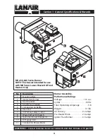
Страница 4: ... Oil Primary Safety Control 8 Waste Oil Fuel Oil Switch 9 Quick Disconnect Receptacle 10 Air Supply Inlet 11 Combustion Blower Motor Burner Assembly Performance Ratings Voltage 115 vac Cycles 60 hz Total Operating Amperage 5 8 Weight 31 lbs Oil Primary 0 2 amps Pre Heater Block 2 6 amps Ignitor Transformer 0 3 amps 10 11 9 8 7 6 5 4 3 2 1 MX 250 300 Series Burner NOTE This burner intended for use ...

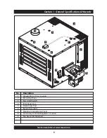
Страница 5: ...lanair com 5 1 3 2 2 2 2 4 8 5 6 7 9 No Description 1 Adjustable Air Flow Louvers 2 Mounting Holes 3 Fan Limit Switch 4 8 Exhaust Flue 5 Flame View Port 6 Burner Assembly 7 Electrical Connections Cover 8 Secondary Air Filter Regulator Location 9 Fan Assembly Internal ...

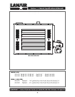
Страница 6: ... 8 00 am 4 15 pm CST 6 MX 250 300 FRONT DIMENSIONS MX 250 Height 36 Width 46 Depth 48 Weight 630 LBS MX 300 Height 36 Width 46 Depth 48 Weight 630 LBS FIRING CAPACITIES MX 250 Nozzle 1 79 gallons hour No 2 fuel oil used crankcase oil MX 300 Nozzle 2 14 gallons hour No 2 fuel oil used crankcase oil ...

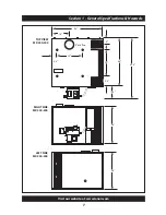
Страница 7: ...Section 1 General Specifications Hazards Visit our website at www lanair com 7 RIGHT SIDE MX 250 300 LEFT SIDE MX 250 300 TOP VIEW MX 250 300 36 36 16 25 24 48 46 13 5 59 5 6 9 5 5 5 8 dia flue ...

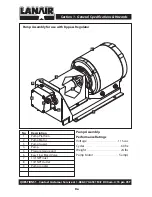
Страница 8: ...tings Voltage 115 vac Cycles 60 hz Weight 24 lbs Pump Motor 5 amps QUESTIONS Contact Customer Service at 1 888 370 6531 M F 8 00 am 4 15 pm CST No Description 1 Pump Platform 2 Pump Motor 3 Pump Guard 4 Pump 5 Pressure Gauge port 6 Easy Flow Bleed Valve 7 1 4 NPT Inlet 8 1 8 NPT Outlet 9 Pump coupler 7 4 3 2 1 5 8 6 9 ...

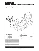
Страница 9: ...ice at 1 888 370 6531 M F 8 00 am 4 15 pm CST No Description 1 Pump Platform 2 Pump Motor 3 Pump Guard 4 Pump 5 Pressure Gauge port 6 Easy Flow Bleed Valve 7 1 4 NPT Inlet 8 1 8 NPT Outlet 9 Pump coupler 10 Line to Burner 11 Line to Tank 7 4 3 1 10 11 5 8 6 9 2 Section 1 General Specifications Hazards Optional Metering Pump Assembly ...

Страница 10: ...TH YOUR HEATER OR ITS INSTALLATION YOU SHOULD CONTACT THE ANAIR USTOMER 3ERVICE EPARTMENT AT s This heater is not designed for attachment or use with ductwork s Do not attempt to start the burner when excess oil oil vapor or fumes have accumulated Never press the red button on the oil primary control more than twice This could cause excess vapor or fuel to ignite causing damage to the heater and o...

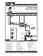
Страница 11: ... Oil Strainer Supply Tank 16 17 19 20 23 14 24 13 12 13 18 25 11 10 9 2 5 1 15 21 22 8 8 11 3 4 6 7 1 Chimney Cap 2 Chimney Pipe 36 3 Storm Collar 4 Roof Flashing 5 Chimney Pipe 36 6 Finishing Collar 7 Slip Connector 14 8 Black Pipe 24 9 Black Tee w cap 10 Barometric Damper 11 Black Pipe 24 12 Burner 13 Union 14 15 Shut off Valve 16 Shut off Valve 17 Suction Line Strainer 18 Fuel Pump 19 Check Val...

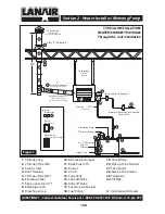
Страница 12: ...nd Oil Strainer Supply Tank 16 17 19 20 23 14 24 13 12 13 18 11 10 9 2 5 1 15 21 22 8 8 11 3 4 6 7 1 Chimney Cap 2 Chimney Pipe 36 3 Storm Collar 4 Roof Flashing 5 Chimney Pipe 36 6 Finishing Collar 7 Slip Connector 14 8 Black Pipe 24 9 Black Tee w cap 10 Barometric Damper 11 Black Pipe 24 12 Burner 13 Union 14 15 Shut off Valve 16 Shut off Valve 17 Suction Line Strainer 18 Fuel Pump 19 Check Valv...

Страница 13: ...op of the fuel supply tank 6 Before suspending the heater check the supporting structure and reinforce if necessary to support the weight of the heater system 7 Use 3 8 steel threaded rod to suspend the heater from a capable load carrying ceiling structure when not using the Lanair Waste Oil Storage Tank 8 The heater must be suspended level for proper operation A heater that is not level could cau...

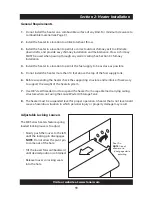
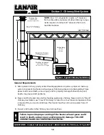
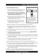
Страница 14: ... damage FOLLOW CHIMNEY MANUFACTURERS INSTRUCTIONS General Requirements 1 Safe operation of any gravity vented heating appliance requires a proper air make up system to prevent the heater exhaust gases from being drawn into the building These gases could cause death serious injury and or property damage Exhaust fans paint booths may cause draft problems 2 Never vent this heater into another heating...

Страница 15: ...raft controls or any other type of restrictive control in the chimney 11 Install clean out tee with a cap at the transition of the chimney FOLLOW CHIMNEY MANUFACTURERS INSTRUCTIONS 12 Use Class A insulated chimney pipe to vent exhaust gases through wall ceilings attics roofs combustibles etc Class A chimney must be used for the entire run once passing through a wall of ceiling 13 Vent chimney at l...

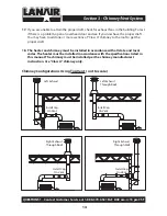
Страница 16: ...chimney to the roof to get the proper draft 18 The heater and chimney must be installed in accordance with all state and local codes The heater must be installed in accordance with the specifications listed in this manual The chimney must be installed per the chimney manufacturer s instruction Use Class A chimney only Chimney Configurations Using Top Vent not to scale Left Exhaust Through Roof Rig...

Страница 17: ...1 2 Pick up Tube not included TOP VIEW Figure 3 The Lanair heater should have a negative 02 draft reading when cold and a negative 06 when hot Check the heater when it is running after 45 minutes If the reading is not what it should be adjust the barometric damper according to the instructions provided with the damper The draft reading should be taken with a manometer Consult your heating contrac ...

Страница 18: ...ure 3 The Lanair heater should have a negative 02 draft reading when cold and a negative 06 when hot Check the heater when it is running after 45 minutes If the reading is not what it should be adjust the barometric damper according to the instructions provided with the damper The draft reading should be taken with a manometer Consult your heating contrac tor or a manometer can be purchased from t...

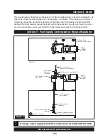
Страница 19: ...er voiding the warranty 5 Pitch the fuel supply 2º with the drain valve at the lowest end to drain off water and sludge Sludge may have to manually be removed 6 Some ordinances may require the fuel supply tank to be vented to outside and above the roofline Check State and Local codes Keep the vent clear 7 Install the fuel tank fill pipe at the end of the tank and above the drain 8 Label the fuel t...

Страница 20: ... thread connections Do Not Use Teflon Tape 8 Install the suction line strainer in the suction line Make sure the suction line strainer is 6 off the bottom of the tank The suction line strainer may be mounted horizontally or ver tically Consider accessibility 9 Install a 1 2 NPT pipe union between the suction line strainer and the pick up tube to allow for service on the pick up tube 10 Install the...

Страница 21: ...s on all copper tubing connections Do not use compression fittings Keep the fuel supply lines 1 off any outside walls The fuel supply line must gradually rise to the burner It should not be higher than the burner Clean all lines fittings and parts internally before assembly A small burr or piece of rust could plug the nozzle See Section 2 for an illustration of a typical pump and piping installati...

Страница 22: ... a filter with a bowl a condensate drain leg must be installed in the air supply line 6 Install a quick disconnect at the air filter regulator on the furnace for service 7 For the ease of installation install a flexible airline 250 I D minimum from the quick disconnect to the primary air regulator 8 The air supply line must be pitched uphill from the primary regulator to the furnace to prevent con...

Страница 23: ...vice to the heater MUST be stranded 12 GA minimum 6 Install a manual service disconnect near the heater and label its function 7 The supply voltage must be maintained at a minimum 110 VAC 8 The electrical conductors from the main electri cal service must be within approved conduit 9 Keep all electrical conductors and conduit away from the chimney connector as well as any other hot surfaces Refer t...

Страница 24: ...E T A E H E R P L I O R E T A E H E R P WHITE ORANGE K C A L B K C A L B E T I H W E T I H W N E E R G D E R E G N A R O D E R N A F K C A L B L L A W T A T S O M R E H T D A C L L E C YELLOW YELLOW BLUE NOT USED LINE IN PUMP MOTOR LINE IN L A U N A M T E S E R T I M I L N A F L O R T N O C T I M I L N A F l l e w y e n o H BLACK RED YELLOW Figure 7 T I M I L N A F L O R T N O C N A F T I M I L WH...

Страница 25: ...T A E H E R P WHITE ORANGE K C A L B K C A L B E T I H W E T I H W N E E R G D E R E G N A R O D E R N A F K C A L B L L A W T A T S O M R E H T D A C L L E C YELLOW YELLOW BLUE NOT USED GREEN BLUE BLACK BLACK BLACK RED L A U N A M T E S E R T I M I L N A F L O R T N O C T I M I L N A F l l e w y e n o H BLACK RED YELLOW Figure 7 T I M I L N A F L O R T N O C N A F T I M I L WHITE YELLOW RED K C A...

Страница 26: ...color code etc Keep the power off until the heater is ready to be started Refer to Section 11 Start Up Procedure Room Thermostat Installation 1 All wiring must comply with the National Electrical Code State and Local Ordinances and be wired by a qualified electrician 2 Install the room thermostat in accordance with the directions furnished with the ther mostat 3 Use two conductor thermostat wire f...

Страница 27: ... Section 14 Trouble Shooting Burner has a 2 minute automatic restart feature s Fan Limit Control The fan limit control performs 3 functions The fan limit control monitors the temperature of the air inside the cabinet When the air reaches a set point usually 120º F it will switch on the heater fan When the temperature in the cabinet drops below 90º F the fan limit control will turn the fan off The ...

Страница 28: ...ements The Snap Disc is mounted on the oil pre heater inside the burner See Page 51 s Nozzle The Nozzle uses air pressure to help pull fuel through its small orifice and to atomize the fuel for proper combustion The Nozzle is located on the end of the air pre heater opposite the fuel valve Replace the Nozzle annually as they are prone to wear by contaminants in waste oil See Page 47 s Fuel By Pass...

Страница 29: ... 3 16 ID clear plastic tubing The tubing should be long enough to allow the fuel to be returned to the tank Turn the room thermostat above room temperature or to the ON position Momentarily disconnect one end of the jumper wire at the F F terminals on the oil primary The fuel pump will now start Observe the clear tubing attached to the bleeder screw on the pump When a steady stream of fuel no air ...

Страница 30: ...el supply line to the burner 14 Remove the jumper wire from the F F terminals on the oil primary control reattach the yellow cad cell wires 15 Adjust the burner air filter regulator to 18 PSI 16 If the fuel supply pump prime or fuel stream has air in it spurting fluctuating flow there is likely a leak in the suction side of the plumbing Refer to section 14 trouble shooting flow chart 2 The burner ...

Страница 31: ...3 seconds 9 Turn the main electrical service ON 10 Flip the lighted rocker switch for preheating on the burner electrical box to the ON posi tion pre heater OFF the light is off pre heater ON the light is on 11 Prime the fuel supply pump Refer to Section 10 Priming the Fuel Supply Pump 12 13 14 Adjust the burner air filter regulator to 18 PSI and the primary air regulator to 30 PSI NOTE 18 PSI on ...

Страница 32: ...NT that the barometric damper is set to the required settings to ensure the natural draft of exhaust gases see section 4 17 Depending on the type of fuel used the elevation temperature and oil viscosity the combustion air baffle will need to be adjusted for optimum performance See page 29 31 flame adjustment 18 When the room thermostat setting is met the burner will shut off but the fan will con t...

Страница 33: ...e Then slowly open the baffle in 1 16 increments until the rumbling stops wait 2 minutes between adjustments finally open the baffle an additional 1 8 to provide excess oxygen Secure the baf fle See Fig 10 NOTE Mechanical equipment like gauges and regulators are not always 100 percent accurate VISUAL INSPECTION OF THE FLAME IS REQUIRED in order to properly dial in the flame settings see page 30 co...

Страница 34: ...AME QUESTIONS Contact Customer Service at 1 888 370 6531 M F 8 00 am 4 15 pm CST Flame Adjustment Visual Flame is over fired Fig 11 t BSL ZFMMPX UP PSBOHF JO DPMPS t 5IF øBNF JT IJUUJOH UIF XBMMT öMMJOH UIF DIBNCFS XJUI B TNPLFZ øBNF PSSFDU JNNFEJBUFMZ PS DIBNCFS NBZ CF EBNBHFE t FDSFBTF GVFM QSFTTVSF XIFO VTJOH B CZ QBTT SFHVMBUPS BOE BEKVTU DPNCVTUJPO BJS 0QFO UIF DPNCVTUJPO BJS CBõF PO UIF TJEF...

Страница 35: ...pressure when using a by pass regulator Solutions 1 Correct fuel pressure setting when using a by pass regulator 2 Flame tips reach 3 4 of the way into the chamber 3 Flame has slightly yellow orange tips 4 No black smoke coming from the chimney 5 Ash inside the chamber is white to off white in color 6 Open combustion air baffle on the side of the burner Flame is full Fig 13 Bright yellow in color ...

Страница 36: ... quate eye face and breathing protec tion MONTHLY s Check combustion chamber and heat exchanger Clean if neccessary Inspect fire brick NOTE Wear protec tive clothing ade quate eye face and breathing protec tion Do not breathe dust from the com bustion chamber Wash thoroughly with soap and water after cleaning chamber s Clean the chimney chimney connector and barometric damper s Clean pump strainer...

Страница 37: ... maintenance Section 13 Service Maintenance Visit our website at www lanair com 33 1 2 3 4 5 6 7 9 3 1 4 1 5 1 8 1 9 1 0 2 2 1 7 1 6 1 1 1 0 1 8 2 2 3 2 This entire pre heater assembly is available Air Pre Heater Breakdown Part 9812 For a Tune Up ...

Страница 38: ...e hex cap screws 17 and set adapter assembly aside 4 Remove Plunger Spring and Cartridge Heater s Remove spring 13 from plunger 15 and clean both pieces s Remove 1 4 o ring 10 and 11 16 o ring 11 s Loosen and remove cartridge heater and set aside 5 Remove Nozzle Assembly and Quad Ring s Remove nozzle assembly 3 using a 5 8 wrench s If quad ring 4 does not come out with nozzle care fully remove it ...

Страница 39: ...nd adjust if necessary see page 39 8 Re install O rings and Plunger s Insert 1 4 o ring 10 and 11 16 o ring 11 into the air pre heater block 5 s Insert plunger into air pre heater block spring end first 9 Re install Cartridge Heater s Apply pipe dope to cartridge heater threads Insert cartridge heater into air pre heater block and tighten 10 Re install Adapter Assembly s Align the holes of the ada...

Страница 40: ...ng 7 2 o ring 5 16 OD 8 8430 1 oil gauge 9 1 hex cap screw 10 1 o ring 1 2 OD 11 1 washer 12 3 plug 13 9533 1 snap disc assembly 14 1 button hex screw Maintenance Oil Pre Heater 1 Separate Air Pre Heater from Oil Pre Heater 10 s Remove o ring 2 Disassemble Oil Pre Heater s Remove six hex cap screws 3 from face plate 2 s Remove oil cartridge heater 1 s Remove four 13 16 OD o rings 4 s Remove three ...

Страница 41: ... pre heater assembly into the burner body s Align the holes of the pre heater assembly with those in the burner body s Secure the assembly to the body by re installing the button hex screw 14 and washer 11 NOTE Do not tighten this screw at this time s Re install oil gauge and oil fitting NOTE Do not tighten these fittings at this time s Adjust the pre heater assembly for proper setting The end of ...

Страница 42: ... heater 2 While holding the lower housing unscrew the center bolt on the top of the suction line strainer 3 Rinse the filter and lower housing in solvent 4 Air dry the strainer and lower housing 5 Re assemble the strainer ensuring the rubber gaskets spring and o rings are in place 6 Fill the lower housing with waste oil or fuel oil 7 Position the lower housing to the top making sure the o ring is ...

Страница 43: ...ate ly 1 8 beyond the end of the nozzle The tips of the one piece ignitor should be 1 8 apart Adjust as required and tighten nut on the top of the ignitor see illustrations for clarification of placement 5 Re assemble pre heater assembly see pages 33 37 carefully re install the pre heater assembly into burner housing The turbula tor should be approximately 1 4 from the end of the burner tube Adjus...

Страница 44: ...ring from the block and inspect Replace if nec essary 5 Insert clean new quad ring into the air pre heater block NOTE The quad ring must be properly seated Failure to properly seat the quad ring may result in leakage and improper burner operation DO NOT INSTALL QUAD RING ON THE NOZ ZLE 6 Lubricate pin seat and re install noz zle Tighten gently Failure to properly seat the quad ring may result in l...

Страница 45: ... 2 Turn off all power to the heater 120 VAC at the main disconnect Place the fan limit switch lever back into the auto position so the fan is off upon restarting 3 Remove the burner and flame view port from the heater Remove the galva nized panel covering the clean out cover remove four 4 10 screws from the top and four 4 10 screws from the bottom of the panel and remove 4 Remove the clean out cov...

Страница 46: ...tal screws Slide the front panel of the unit to the right side of the heater far enough to expose the manifold clean out port 10 On the left side facing the front of the unit remove the 4 10 sheet metal screws from the manifold clean out ports Using an industrial type canister vacuum cleaner with a high efficiency filter remove all ash accumulation 11 The chimney connector can also be removed to a...

Страница 47: ...m the by pass regulator assembly 3 Disassemble the by pass regulator and discard the small plug spring large plug washer and diaphragm 4 Thoroughly clean and dry remaining parts 5 Re assemble using new small plug spring large plug washer and diaphragm Kit P N 9874 NOTE Pay close attention to the posi tions of the large and small plugs adjusting screw locking nut cap small plug spring large plug wa...

Страница 48: ...ill the jar above the open end of the tubing t If the pump will not pump fuel attempt to prime the pump Section 10 If the pump won t prime refer to Flow Chart Item B If no air or water is present the flow must be determined t When using a by pass regulator pump fuel for 1 minute into a graduated container if the flow rate is less the 250 MILS Minute 8 1 2 Ounces refer to Section 14 Troubleshooting...

Страница 49: ...Adjust the heater air filter regulator to 0 PSI Install jumper wire Vacuum Gauge reading hints No reading 0 1 HG s Pump not operating s Pump air locked and needs priming Refer to section 10 s Vacuum leak Pump shaft seal Pump cover gasket Suction strainer gaskets Low fuel level in tank Pipe connections suction side Strainer in pump cover Low to normal reading 1 6 inches HG s Pump operating properly...

Страница 50: ... plugged Reading drops to 0 PSI when the burner is off s Dirt between the diaphragm and the seat in the by pass regulator when using a by pass regulator s Dirt between the plunger and the nozzle seat s Leak in the plumbing connections s Leak in the pre heater assembly damaged or missing o ring s Fuel pre heater switch is off Steps to check the air operated fuel valve s Disconnect the two transform...

Страница 51: ...ablish a contaminated fuel clean tank flame 2 Plugged or worn nozzle 2 Clean or replace 3 Fuel pressure gauge 3 See section 6 Page 17 fluctuating pumping system 4 Pre heater switch is turned off 4 Turn switch on or test or defective or defective switch and cartridge heater cartridge heater 5 Transformer electrodes not 5 Test transformer look r i a p e r s t r o h s r o f g n i k r a p s Replace el...

Страница 52: ... See flame adjustment pressure fluctuating pages 29 31 See fuel piping page 17 6 Improper combustion blower 6 See flame adjustment setting or blower is defective pages 29 31 See fuel piping page 17 7 Oil primary cad cell defective 7 Test components adjust Cad cell improperly adjusted cad cell clean turbulator Dirty flame turbulator 8 Plugged nozzle or pre heater 8 Clean nozzle and or y l b m e s s...

Страница 53: ...of the initial shipment 5 All authorized returns will be fully refunded less restocking fees shipping and handling charges 6 To obtain an authorization number please call our customer service department at 1 888 370 6531 or email us at service lanair com 7 All authorized returns must have the authorization number marked on the outside of the package and returned to the following address Lanair Pro...

Страница 54: ...y s Any portion of the combustion chamber heat exchanger if NOTE Re stocking fee of 20 applies on all returned parts NOTE Lanair may require photographs of the heater installation for warranty determination The unit is not installed per the owners manual The yearly inspection requirements are not current If the heater is used for a purpose for which it is not intended If the heater is not operated...

Страница 55: ...e Manual Reset Snap Disk Fuel Supply Pre Heater Adjustment Screw To Combustion Blower Pre Heater Switch Air Supply Air Supply Air Solenoid Ignitor Oil Pre Heater Block Air Pre Heater Block To Oil Primary To F Terminals To Transformer Burner Cover View Port Cad Cell Electrical Quick Disconnect ...

Страница 56: ...009 Lanair Products LLC Lanair is a registered trademark of Lanair Products LLC Part 5031 REV 21a 11 16 10 Lanair Products LLC 4109 Capital Circle Janesville Wisconsin 53546 1 888 370 6531 www lanair com ...

Отзывы: