190
7
Operating Control and Displays
Configuration
The first step in deploying a CMS is to register the individual modules with the system
. This provides the system with details of the modules' serial numbers, functions and number
. This data is then saved and filed as a dataset.
Normally, the modules included in the delivery are already registered with the system and
shown highlighted in green in the module management window. New modules, or modules
that replace existing modules or expand the system must be registered first. If multiple mod-
ules with the same function are included in the system, each module is issued with a unique
number by module management so they cannot be mixed up.
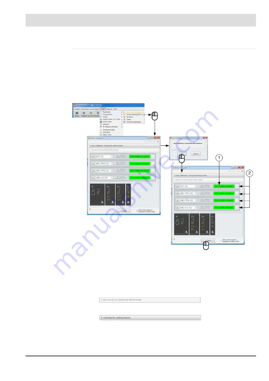
Fig. 7-68 Module registration procedure
Module registration
1. Click the
button.
The system searches for existing modules and identifies and new modules not yet regis-
tered.
2. Click the
button.
The system is ready to register new and unfamiliar modules. The drop-down menus for
the registration process are active.
The I/O matrix is used to assign physical or logic signals to the input and output functions of
the CMS. Some of these signals are mandatory and some are optional. Apart from signal as-
1
Bright green: Module is present and registered.
Dark green: Module is present and not registered.
Red: Module no longer present (should be removed in order to avoid faults)
2
Register and deregister buttons
Содержание AEC-TPS
Страница 1: ...www lamtec de Sensors and Systems for Combustion Engineering Manual Combustion Management System CMS...
Страница 2: ......
Страница 42: ...41 4 CMS Components 4 2 5 Terminal Assignment Fig 4 9 AEC TPS 230 VAC or 120 VAC terminal assignment...
Страница 131: ...130 7 Operating Control and Displays 7 1 5 5 Deleting Curves Delete firing rate curve...
Страница 142: ...141 7 Operating Control and Displays Accessing channel information AL1 Fig 7 12 GUI6xx channel information...
Страница 148: ...147 7 Operating Control and Displays Channel configuration AL1 Fig 7 18 Channel configuration...
Страница 154: ...153 7 Operating Control and Displays Accessing the CO O2 settings AL2 Fig 7 24 CO O2 settings menu...
Страница 157: ...156 7 Operating Control and Displays Fig 7 27 System CRCs menu...
Страница 162: ...161 7 Operating Control and Displays Fig 7 32 IP setting menu...
Страница 163: ...162 7 Operating Control and Displays 7 2 8 User Settings Accessing the display settings Fig 7 33 Display settings menu...
Страница 164: ...163 7 Operating Control and Displays Accessing the language settings AL1 Fig 7 34 Language settings menu...
Страница 166: ...165 7 Operating Control and Displays Fig 7 35 Installation...
Страница 167: ...166 7 Operating Control and Displays Fig 7 36 Installation...
Страница 176: ...175 7 Operating Control and Displays Fig 7 49 Loading a protected dataset into the device...
Страница 198: ...197 7 Operating Control and Displays 1 Digital inputs 2 Digital outputs 3 PLC Signals 4 Analogue measurement values...
Страница 202: ...201 7 Operating Control and Displays Replacing a Module Fig 7 81 Module replacement menu...
Страница 271: ...270 10 Maintenance 6 Close the window Connection between PC and CMS is established Indication of the con nected CMS...
Страница 272: ...271 10 Maintenance How to update the firmware in the CMS AL2 1 Open the menu Firmware update 2 Prepare firmware update...
Страница 274: ...273 10 Maintenance Activating the Debug Data 1 Start CMS Remote Software 2 Set device online 3 Show debug data...
Страница 276: ...275 10 Maintenance 3 Restart CMS to complete the update...
Страница 282: ...281 12 Appendix 12 5 EU Declaration of Conformity...
Страница 283: ...282 12 Appendix...


