


KYRA D 30 SI UNIT COND
A73022660
44
EN
A
Starting without pre-heater
B
Flame present
C
Normal operation
D
Adjustment stop (TA-TC)
t1
Pre-ventilation
time
TSA
Safety time
t3
Pre-ignition
time
t3n
Post-ignition
time
tw
Pre-heating
time
Output signals from the unit
Necessary input signals
Checks during operation
• Ignite the appliance as described in sec.2.3.
• Check that the fuel circuit and water systems are airtight.
• Check the ef
fi
ciency of the
fl
ue and air-fume ducts while the boiler is working.
• Check that the water is circulating properly between the boiler and the systems.
•
Check the proper ignition of the boiler by performing various tests, turning it on
andoff with the room thermostat or remote control.
• Check that the burner door and fume chamber are tight.
• Check that the burner works properly.
•
Analyse the combustion (with the boiler unit stable) and check that the content
of CO2 in the fumes is between 11% and 12%.
• Check the parameters are programmed correctly and perform any required cus-
tomization (compensation curve, power, temperatures, etc.).
4.3 Maintenance
Periodical check
To ensure correct operation of the unit over time, have quali
fi
ed personnel carry out
ayearly check, providing for the following:
• The control and safety devices must function correctly.
• The fume exhaust circuit must be perfectly ef
fi
cient.
•
Check there are no obstructions or dents in the fuel supply and return pipes.•-
Clean the
fi
lter of the fuel suction line.
• Measure the correct fuel consumption
• Clean the combustion head in the fuel outlet zone, on the swirl disc.
• Leave the burner running at full rate for approximately ten minutes, then analy-
sethe combustion, checking:
- All the elements speci
fi
ed in this manual are set correctly
- Temperatures of the fumes at the
fl
ue
- CO2 percentage content
• The air-fume end piece and ducts must be free of obstructions and leaks
•
The burner and exchanger must be clean and free of deposits. For possible
cleanng do not use chemical products or wire brushes.
• The gas and water systems must be airtight.
•
The water pressure in the cold water system must be approx. 1 bar; otherwise,
bringit to that value.•The circulating pump must not be blocked.
• The expansion tank must be
fi
lled.
• Check the magnesium anode and replace it if necessary.
The boiler casing, control panel and aesthetic parts can be cleaned with
a softand damp cloth, if necessary soaked in soapy water. Do not use
any abrasivedetergents and solvents.
Cleaning the boiler
1. Disconnect the power supply to the boiler.
2. Remove the upper panel
“A”
and open the burner door.
3. Unscrew the nuts
“B”.
4. Remove the cover from the smoke chamber
“E”.
5. 5. Remove the turbulators
"C"
.
6. Wipe the outlet of the fumes with a brush
“D”
and an aspirator.
7. Remove all residues from the combustion chamber.
8. Reassemble all removed components.
A
B
E
C
D
fi
g.32
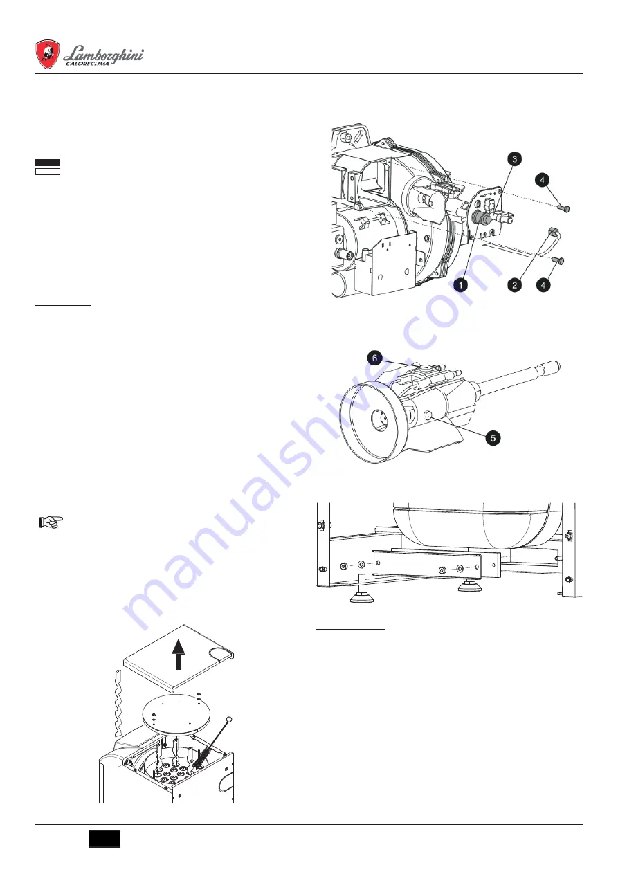
Accessing the electrode and nozzle
• Disconnect the transformer electrode cables and remove the photoresistance
1,
andt he union
2
connecting the oil pipe to line
3
of the nozzle. Loosen the screws
4
andpull out the nozzle-baf
fl
e-electrode
fl
ange assembly.
fi
g.33
•
Undo
the
screw
5
to remove the baf
fl
e and screw
6
to remove the electrodes.
Propercleaning of the nozzle is obtained by removing the
fi
lter and cleaning the
slots andspraying hole with petrol, rinsing it with fuel oil. When reassembling
everything, payattention to the correct positioning of the electrodes-baf
fl
e.
fi
g.34
Condensate tank
To access the condensate tank, open the lower cover (Fig. 35).
fi
g.35
4.4 Troubleshooting
Diagnostics
The boiler is equipped with an advanced self-diagnosis system. In case of a boiler
fault, the display will
fl
ash together with the fault symbol (9 -
fi
g.1) indicating the
faultcode.
There are faults the cause permanent shutdowns (marked with the letter
“A”
): to
restore operation, just press the
RESET
button (3 -
fi
g.1) for 1 second or use the
RE-
SET
on the remote timer control (optional) if installed; if the boiler does not restart, it
is necessary to eliminate the fault indicated in the operation LEDs.
Other faults cause temporary shutdowns (marked with the letter
“F”
) which are
automatically reset as soon as the value returns within the boiler’s normal working
range.


