background image

15

BOILER INSTALLATION

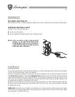
UNPACKING THE BOILER

1

Open the top of the carton and remove the
following parts:
Boiler tools and accessory pack
Document pack and wall template
Wall mounting template
Down-draft diverter

2

Break open the boiler carton with care. 

Do not

cut the carton, open with a knife: you could
damage the jacket.
Make sure that the surface on which the carton is
resting is protected so the boiler is not scratched
or damaged during unpacking.

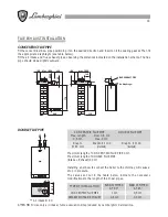
PREPARING THE WALL

1

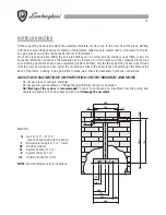
Use the supplied template to decide on boiler
positioning.
The template is the same size as the boiler plus
the spaces which need to be maintained around
it.

Note

: When deciding on boiler position take into

account the flue terminal position.

2

Attach the template to the wall with adhesive tape
(make sure it is level) and mark the position of
the two holes used to fix the bracket to the wall,
the two holes for the upper part of the boiler and,
in the case of a rear-mounted fume outlet, the
flue hole.
If there is to be a side flue continue with the central
horizontal line of the flue along the wall towards
the side wall and then along the side wall for
160 mm. This is the position of the centre of the
flue hole.

3

Cut the 105 mm flue hole in the wall. Make sure
that it is horizontal. Drill the four fixing holes:
these must be suitable for the n. 9 plugs (supplied).
Fit the plugs.

4

Fix the assembly bracket to the wall with the two
supplied screws. Make sure that it is level and
fitted the right way round.

Template

Position of
105 mm
hole to be
prepared
for side
flue

160

Wall
bracket

Side
wall

Содержание Xilo T 20 MS W TOP

Страница 1: ...NSTALLATION AND MAINTENANCE MANUAL PLEASE MAKE SURE THAT THE USE MANUAL IS HANDED OVER TO THE USER 20MSWTOP IE CERTIFICATED COMPANY ISO 9001 WALL HUNG GAS BOILER FOR HEATING HIGH EFFICIENCY MODULATING...

Страница 2: ......

Страница 3: ...give important safety instructions regarding installation and maintenance Keep this manual for future reference Installation must be carried out by qualified personnel who will be responsible for res...

Страница 4: ..._________________________________8 GAS NOZZLE CALIBRATION ____________________________________________9 ELECTRICAL CONNECTIONS WIRING DIAGRAMS _______________________ 10 MALFUNCTIONS AND ADJUSTMENTS _...

Страница 5: ...bags foam etc must not be left within reach of children as they are potential sources of danger This boiler is designed to heat water to a temperature below boiling atmospheric pressure It must be co...

Страница 6: ...no water pressure switch total safety thermostat high efficiency bi thermal flue gas exchanger Hot water plate exchanger XILO T 20 MS W TOP Equipped with electronic control unit for automatic ignitio...

Страница 7: ...10 Safety valve 11 Circulator 12 Filling cock 13 Gas valve 14 Modulating coil 15 Gas pressure reading point 16 Expansion tank 17 Thermohydrometer 18 Malfunction warning light 19 ON OFF warning light...

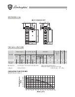
Страница 8: ...as 20 mbar Category II 2H3 II 2H3P B 28 30 mbar P 37 mbar TECHNICAL FEATURES Residual pressure mbar Delivery l h XILO T 20 MS W TOP 100 Max 3000 220 85 440 770 100 Max 3000 160 330 MODEL XILO T 20 MS...

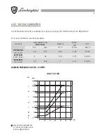
Страница 9: ...20mbar LIQUID GAS B G30 28 30mbar LIQUID GAS P G31 37mbar Jets pressure mbar Slow ignition adjustment 2 7 mbar NATURAL GAS 6 mbar LIQUID GAS Burner jets mm 1 25 0 77 0 77 L C V kcal h 8 550 29 330 22...

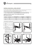
Страница 10: ...nstallation must be made in compliance with safety REGULATIONS IN FORCE Make a good earth connection To gain access to the electrical panel which houses the power supply terminal block and any connect...

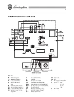
Страница 11: ...ating coil CiR Heating circulator EA Ignition electrode EC Control electrode F Fuse JP1 Methane LPG selector JP3 Post circulation selector JP4 Ignition limiting selector JP5 Jumper to be cut for low t...

Страница 12: ...floor heating temp set to 30 40 C Resistor jumper uncut temperature 35 80 C increase increase Legend Off On Slow ignition adjustment Max heating power adjustment Should the boiler shut down it must b...

Страница 13: ...l as well as an opening for the connections Attach the boiler to the hooks through the holes at the back of the frame pushing it up against the finished wall Make the necessary hydraulic connections A...

Страница 14: ...ting sensor 4 Gas valve 5 Filling cock 6 Safety valve 7 No water pressure switch 8 Circulator 9 Burner 10 Expansion tank 11 Fumes pressure switch 12 Fan 13 Automatic air bleed valve 14 Total safety th...

Страница 15: ...unt the flue terminal position 2 Attach the template to the wall with adhesive tape make sure it is level and mark the position of the two holes used to fix the bracket to the wall the two holes for t...

Страница 16: ...or a flexible stainless steel pipe with continuous wall of the approved type The flexible corrugated metal pipes must be installed in such a way that their length in a state of maximum extension is n...

Страница 17: ...8 5 6 CONNECTION TO THE CHIMNEY VERSION XILO T 20 MS W TOP The boiler is for combustion in a sealed chamber and does not require any special ventilation it can also be located in small rooms lumber ro...

Страница 18: ...ngth of CONCENTRIC FLUE PIPE 3 mt Maximum length of DOUBLE FLUE PIPE Intake Exhaust 20 mt Installing an elbow to connect the boiler to the chimney will cause a drop in pressure The values set out in t...

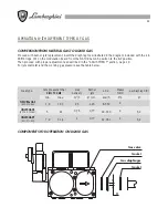
Страница 19: ...or gas delivery may be obtained from a double modulator coil Calibration of the slow ignition pre calibrated in the factory is electronically done and is adjustable for optimising and for gas type con...

Страница 20: ...ific conditions of installation and use but it is advisable to have the unit checked once a year by authorised Lamborghini Service personnel Only properly qualified personnel with specific knowledge i...

Страница 21: ...r ignition shutdown and operation of both hot water and heating functions checking for proper seal on gas water fittings and pipes checking gas consumption at minimum and maximum power checking positi...

Страница 22: ...hragm as illustrated in the diagram included with the kit Shift bridge JP1 on the modulation board from the NATURAL GAS position to the B P position Then proceed with proper adjustment as described in...

Страница 23: ...technical service A Flue cross section or height with joint not suitable for the boiler B Excessive gas consumption combustion is imperfect C Flames tend to detach D Flames have yellow tips A Replace...

Страница 24: ...24...

Страница 25: ...25...

Страница 26: ...26...

Страница 27: ......

Страница 28: ...EXPORT 0532 359947 Le illustrazioni e i dati riportati sono indicativi e non impegnano La LAMBORGHINI si riserva il diritto di apportare senza obbligo di preavviso tutte le modifiche che ritiene pi op...

Отзывы: