


33
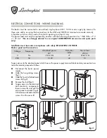
WATER CONNECTION
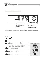
Fit the supporting hooks and attach the assembly template, moving it up to the wall; fit all the pipes,
starting with the end pipe fittings already mounted on the template: system supply, system return, cold
water, hot water, any gas pipes and electric mains leads with room thermostat.
Once the pipes have been fitted, the end pipe fittings can be removed and ordinary caps fitted, ready
for hydraulic tests to be carried out. The template can be removed or, if left in place, will be embedded
in the wall once finishing operations have been completed (plaster and tiles); only the two supporting
hooks will protrude from the wall, as well as an opening for the connections. Attach the boiler to the
hooks through the holes at the back of the frame and push it up against the finished wall. Make the
necessary hydraulic connections.
ADVICE AND SUGGESTIONS ON PREVENTING SYSTEM VIBRATION AND NOISE
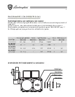
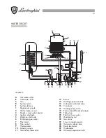
126
226
452
21,5
900
600
476
62
GS
62
M
R
AE
C
G
F
24,5
854
304
382
522
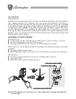
-
Do not use pipes of reduced diam-
eter.
-
Do not use low-radius elbows or fit-
tings that significantly reduce cross-
section.
-
Hot-flushing of the system is recom-
mended
in order to eliminate any
impurities from the piping and radia-
tors (especially oil and grease) which
might
damage the circulator
.
LEGEND
C
Hot water Ø 1/2”
G
Gas Ø 1/2” - Ø 3/4” (see tap
supplied with the boiler)
F
Boiler water supply Ø 1/2" (cold)
AE
Electrical supply
M
System delivery Ø 3/4"
R
System return Ø 3/4"
GS
Holding hooks Ø10 mm.
NOTE: Provide female water connections.