background image

1. Instructions d’utilisation .......................................................................38

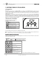
1.1 Présentation ..........................................................................................................38
1.2 Panneau de commandes .......................................................................................38
1.3 Allumage et extinction ..........................................................................................39
1.4 Réglages ................................................................................................................39

2. Installation ............................................................................................39

2.1 Dispositions générales ..........................................................................................39
2.2 Lieu d’installation ..................................................................................................39
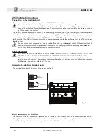
2.3 Raccordements hydrauliques ................................................................................40
2.4 Raccordement gaz ................................................................................................40
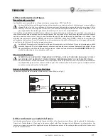
2.5 Raccordements électriques ..................................................................................41
2.6 Raccordement au conduit de fumée ....................................................................41

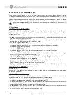
3. Service et entretien ..............................................................................42

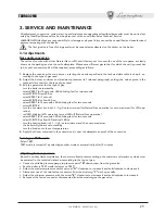
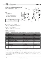
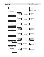
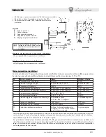
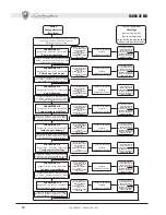
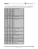
3.1 Réglages ................................................................................................................42
3.2 Mise en service .....................................................................................................46
3.3 Entretien ...............................................................................................................46
3.4 Solution des pannes ..............................................................................................48

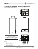
4 Caractéristiques et données techniques ................................................49

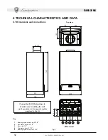
4.1 Dimensions et raccordements ..............................................................................49
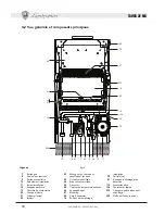
4.2 Vue générale et composants principaux ..............................................................50
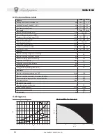
4.3 Tableau des caractéristiques techniques..............................................................51
4.4 Diagrammes ..........................................................................................................51
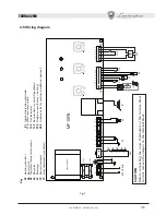
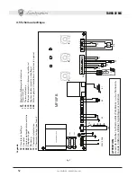
4.5 Schéma électrique .................................................................................................52

TAURA 32 MC

37

Cod. 3540F130 - 03/2007  (Rev. 00)

Содержание Taura 32 MC

Страница 1: ...ENTRETIEN INSTRUCCIONES PARA EL USO LA INSTALACI N Y EL MANTENIMIENTO INSTRU ES DE UTILIZA O INSTALA O E MANUTEN O I A CALDAIA MURALE A GAS PER SANITARIO E RISCALDAMENTO WALL MOUNTING GAS BOILER FOR H...

Страница 2: ...e possono causare danni a persone animali o cose esclusa qualsiasi responsabilit del costruttore per i danni causati da errori nell installazione e nell uso e comunque per inosservanza delle istruzion...

Страница 3: ...gamento gas 6 2 5 Collegamenti elettrici 7 2 6 Collegamento alla canna fumaria 7 3 Servizio e manutenzione 8 3 1 Regolazioni 8 3 2 Messa in servizio 12 3 3 Manutenzione 12 3 4 Risoluzione dei problemi...

Страница 4: ...sanitaria ad alto rendimen to funzionante a gas naturale o GPL dotato di bruciatore atmosferico ad accensione elettronica termostato fumi sistema di controllo a microprocessore destinato all installaz...

Страница 5: ...ione di caricamento ad impianto freddo letta sull idrometro caldaia deve essere di circa 1 0 1 5 bar Se la pressione dell impianto scende a valori inferiori al minimo agendo sul rubinetto di caricamen...

Страница 6: ...liquidi antigelo additivi e inibitori solo ed esclusivamente se il produttore di suddetti liquidi o additivi fornisce una garanzia che assicuri che i suoi prodotti sono idonei all uso e non arrecano...

Страница 7: ...e dotati di un interruttore bipolare i cui contatti abbiano una apertura di almeno 3 mm interponendo fusibili da 3A max tra caldaia e linea E importante rispettare le polarit LINEA cavo marrone NEUTR...

Страница 8: ...zionare INVERNO led rosso acceso selezionare RESET per 1 secondo selezionare INVERNO led giallo acceso selezionare RESET per 5 secondi leds lampeggianti veloce per per due secondi selezionare INVERNO...

Страница 9: ...allatore Men parametri installatore La scheda dotata di 11 parametri trasparenti modificabili sia da Comando Remoto men parametri Service che dalla stessa Men Parametri Installatore ad eccezione degli...

Страница 10: ...nverno al lampeggio velo ce dei tre leds Ruotare Manopola Sanitario per impostare il valore Selettore in Reset e poi di nuovo in Inverno per passare al successivo PARAMETRO N 4 Rosso OFF Verde ON Gial...

Страница 11: ...lito il parametro da settare necessario utilizzare le successive tabelle di conversione per capire in base al lampeggio dei leds che valore si st impostando Con OFF s intende Led spento con ON s inten...

Страница 12: ...l combustibile indicato al contatore corrisponda a quello indicato nella tabella dati tecnici al cap 4 Assicurarsi che senza richiesta di riscaldamento il bruciatore si accenda correttamente all apert...

Страница 13: ...ndere 10 15 minuti per far giungere la caldaia in stabilit 5 Effettuare la misura Analisi effettuate con caldaia non stabilizzata possono causare errori di misura Apertura del mantello Per aprire il m...

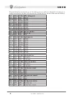
Страница 14: ...osso Sensore riscaldamento danneggiato Mancanza di circolazione d acqua nell impianto Presenza aria nell impianto Controllare che l afflusso di gas alla caldaia sia regolare Controllare il cablaggio d...

Страница 15: ...re Legenda 1 Mandata impianto riscaldamento 3 4 2 Uscita acqua sanitaria 1 2 3 Entrata gas 1 2 4 Entrata acqua sanitaria 1 2 5 Ritorno impianto riscaldamento 3 4 In caso si usi il kit allacciamento id...

Страница 16: ...sicurezza 19 Camera combustione 20 Gruppo bruciatori 21 Ugello principale 22 Bruciatore 27 Scambiatore in rame per riscal e sanitario 32 Circolatore riscaldamento 36 Sfiato aria automatico 38 Flussost...

Страница 17: ...ento C 90 Pressione massima di esercizio riscaldamento bar 3 Pressione minima di esercizio riscaldamento bar 0 8 Capacit vaso di espansione litri 10 Pressione di precarica vaso di espansione bar 1 Con...

Страница 18: ...e riscaldamento 38 Flussostato 42 Sensore di temperatura sanitario 44 Valvola gas 47 Modureg 72 Termostato ambiente 73 Termostato antigelo opzionale 81 Elettrodo d accensione rivelazione 114 Pressosta...

Страница 19: ...or poor maintenance can cause damage or physical injury The manufacturer de clines any responsibility for damage caused by er rors in installation and use or by failure to follow the manufacturer s in...

Страница 20: ...nstallation 22 2 3 Plumbing connections 23 2 4 Gas connection 23 2 5 Electrical Connections 24 2 6 Connection to the flue 24 3 Service and maintenance 25 3 1 Adjustments 25 3 2 System start up 29 3 3...

Страница 21: ...efied petroleum gas equipped with an open flue burner with electronic ignition airtight chamber with forced ventilation and a microprocessor control system and designed for installation indoors or out...

Страница 22: ...must be about 1 0 1 5 bar If the system pressure falls to values below the minimum bring it back to the initial value by operating the filling cock see fig 7 part 74 At the end of the operation alway...

Страница 23: ...luid additives and inhibitors only if the manufacturer of these fluids or additives guarantees they are suitable for this use and cause no damage to the heat exchanger or other components and or mater...

Страница 24: ...n and equipped with a bipolar switch whose contacts have a minimum opening of at least 3 mm interposing fuses of max 3A between the boiler and the line It is important to respect the polarities LINE b...

Страница 25: ...WINTER red LED on select RESET for 1 second select WINTER yellow LED on select RESET for 5 seconds LEDs blinking fast for two seconds select WINTER turn the hot water knob ref 2 fig 1 onto minimum fo...

Страница 26: ...minutes 1 2 5 minutes 6 Heating user max setpoint 30 C 40 C 85 C 85 C 7 Hot water user max setpoint 0 55 C 1 65 C 0 55 C 8 Heating sensor selection 0 Double sensor 1 Safety Therm Sensor 1 Double sens...

Страница 27: ...5 seconds turn to Winter when the 3 LEDs blink fast Selector turned to Reset for 5 seconds turn to Winter when the 3 LEDs blink fast Selector turned to Reset for 5 seconds turn to Winter when the 3 L...

Страница 28: ...election OFF OFF OFF Natural gas ON BL OFF OFF LPG Red Green Yellow Lighting power OFF OFF OFF 00 06 ON BL OFF OFF 06 13 OFF OFF ON BL 13 21 ON BL OFF ON BL 21 29 OFF ON BL OFF 29 36 ON BL ON BL OFF 3...

Страница 29: ...remote control Make sure that the fuel consumption indicated on the meter corresponds to that given in the technical data table in chap 4 Make sure that with no call for heating the burner correctly...

Страница 30: ...out any operation inside the boiler disconnect the electrical power supply and close the gas cock upstream Combustion analysis To analyse the combustion you must 1 Insert the probe in the flue 2 Open...

Страница 31: ...hermostat trips after the fume thermostat trips boiler operation is disabled for 20 minutes Low system pressure Delivery sensor fault Tap water sensor fault Fault Possible cause Cure Green Yellow Red...

Страница 32: ...nections Fig 5 Top view Bottom view Key 1 Heating system delivery 3 4 2 Hot water outlet 1 2 3 Gas inlet 1 2 4 Tap water inlet 1 2 5 Heating system return 3 4 If using the LEJ LINE plumbing kit the di...

Страница 33: ...2 Burner 27 Copper exchanger for heating and hot water 32 Heating circulator 36 Automatic air vent 38 Flow switch 42 Tap water temperature sensor 44 Gas valve 47 Modureg 56 Expansion tank 74 Heating s...

Страница 34: ...Maximum working pressure in heating bar 3 Minimum working pressure in heating bar 0 8 Expansion tank capacity litres 10 Expansion tank pre filling pressure bar 1 Boiler water content litres 1 2 Energy...

Страница 35: ...2 Heating circulator 38 Flow switch 42 Tap water temperature sensor 44 Gas valve 47 Modureg 72 Room thermostat 73 Frost thermostat not fitted 81 Ignition detection electrode 114 Water pressure switch...

Страница 36: ...des choses Le constructeur n assume aucune responsabilit pour les domma ges caus s par des erreurs d installation et d utilisa tion et dans tous les cas en cas de non observation des instructions qu...

Страница 37: ...ent gaz 40 2 5 Raccordements lectriques 41 2 6 Raccordement au conduit de fum e 41 3 Service et entretien 42 3 1 R glages 42 3 2 Mise en service 46 3 3 Entretien 46 3 4 Solution des pannes 48 4 Caract...

Страница 38: ...ut rendement fonctionnant au gaz naturel ou liquide dot d un br leur atmosph rique allumage lectronique et d une chambre tanche ventilation forc e command par un syst me avanc de contr le par micropro...

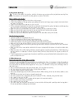
Страница 39: ...p 2 3 1 4 R glages R glage de la pression hydraulique de l installation La pression de charge de l installation froide lue sur l hydrom tre de la chaudi re doit tre d environ 1 0 1 5 bar Au cas o au c...

Страница 40: ...t exclusivement si le producteur de ces liquides ou additifs fournit une garan tie qui assure que ses produits sont idoines l utilisation et ne provoquent pas de dommages l changeur de la chaudi re ou...

Страница 41: ...ire dont les contacts ont une ouverture d au moins 3 mm et avec fusibles de max 3A intercal s entre la chaudi re et le r seau Il est important de respecter la polarit LIGNE c ble marron NEUTRE c ble b...

Страница 42: ...nt 5 secondes clignotements rapides des LED pendant 2 secondes s lectionner HIVER tourner le s lecteur du sanitaire rep 2 fig 1 en le positionnant sur minimum pour le fonctionnement au gaz naturel ou...

Страница 43: ...mage 0 60 50 4 Temps d attente chauffage 0 0minute 1 2 5 minutes 1 2 5 minutes 5 Post balayage pompe de chauffage 0 0minute 1 2 5 minutes 1 2 5 minutes 6 Consigne maxi chauffage 30 C 40 C 85 C 85 C 7...

Страница 44: ...sur Hiver au clignotement rapide des 3 LED Tourner le s lecteur en le positionnant sur Reset pendant 5 secondes positionner ensuite sur Hiver au clignotement rapide des 3 LED Tourner le s lecteur en l...

Страница 45: ...L 85 100 Rouge Vert Jaune S lection du type de gaz OFF OFF OFF Gaz naturel ON BL OFF OFF GPL Rouge Vert Jaune Puissance d allumage OFF OFF OFF 00 06 ON BL OFF OFF 06 13 OFF OFF ON BL 13 21 ON BL OFF O...

Страница 46: ...compteur correspond bien celle indiqu e dans le tableau des caract ristiques techniques chap 4 V rifier qu en l absence de besoins thermiques fonctionnement en chauffage le br leur s allume correctem...

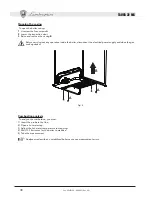
Страница 47: ...r de la chaudi re d brancher l alimentation lectrique et fermer le robinet des gaz en amont Analyse de la combustion Pour l analyse de la combustion il faut 1 Introduire la sonde dans la chemin e 2 Ou...

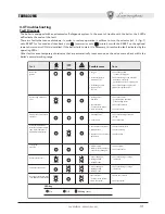
Страница 48: ...lie au capteur d eau chaude sanitaire Anomalie Causes probables Solution Vert Jaune Rouge Capteur de chauffage endommag Absence de circulation d eau dans l installation Pr sence d air dans l installat...

Страница 49: ...ous L gende 1 Refoulement installation chauffage 3 4 2 Sortie eau sanitaire 1 2 3 Entr e gaz 1 2 4 Entr e eau sanitaire 1 2 5 Retour installation chauffage 3 4 En cas d utilisation du kit de brancheme...

Страница 50: ...upape de s ret 19 Chambre de combustion 20 Groupe br leurs 21 Gicleur principal 22 Br leur 27 Echangeur en cuivre pour chauffage et sanitaire 32 Circulateur chauffage 36 Event air automatique 38 Fluxo...

Страница 51: ...gime en chauffage C 90 Pression maximum de r gime en chauffage bar 3 Pression minimum de r gime chauffage bar 0 8 Capacit vase d expansion litres 10 Pression de pr charge vase d expansion bar 1 Conten...

Страница 52: ...brancher le thermostat d ambiance ou la chronocom mande distance liminer le pontage sur le bornier fig 7 L gende 32 Circulateur chauffage 38 Fluxostat 42 Capteur de temp rature sanitaire 44 Soupape de...

Страница 53: ...ar da os ma teriales o personales El fabricante no se hace res ponsable por los da os provocados por una instalaci n o un uso incorrectos y en cualquier ca so por el incumplimiento de las instruccione...

Страница 54: ...56 2 3 Conexiones hidr ulicas 57 2 4 Conexi n del gas 57 2 5 Conexiones el ctricas 58 2 6 Conexi n a la chimenea 58 3 Servicio y mantenimiento 59 3 1 Regulaciones 59 3 2 Puesta en servicio 63 3 3 Mant...

Страница 55: ...anitaria alimentado con gas natural o GLP y dotado de quemador atmosf rico con encendido electr nico c mara estanca con ventilaci n forzada y sistema de control con microprocesador para instalarse en...

Страница 56: ...ticongelante apropiado en el circuito de calefacci n seg n lo indicado en el cap 2 3 1 4 Regulaciones Regulaci n de la presi n hidr ulica de la instalaci n La presi n de carga con la instalaci n fr a...

Страница 57: ...i n de que el fabricante de dichos productos garantice que est n indicados para este uso y que no da an el intercambiador de la caldera ni ning n otro componente o material del aparato o de la instala...

Страница 58: ...ija y un interruptor bipolar cuyos contactos tengan una apertura no inferior a 3 mm interponiendo unos fusibles de 3 A como m ximo entre la caldera y la l nea Es importante respetar la polaridad de la...

Страница 59: ...an r pidamente durante dos segundos seleccionar INVIERNO girar el mando del agua caliente sanitaria ref 2 fig 1 hasta el m nimo para funcionamiento con gas Metano o hasta el m ximo para funcionamiento...

Страница 60: ...2 5 minutos 1 2 5 minutos 5 Postcirculaci n bomba calefacci n 0 0 minutos 1 2 5 minutos 1 2 5 minutos 6 Temperatura m xima calefacci n usuario 30 40 85 C 85 C 7 Ttemperatura m xima sanitaria usuario...

Страница 61: ...ante 5 segundos poner en Invierno cuando los tres testigos parpadeen r pidamente Selector en posici n Reset durante 5 segundos poner en Invierno cuando los tres testigos parpadeen r pidamente Selector...

Страница 62: ...del tipo de gas OFF OFF OFF METANO ON BL OFF OFF GLP Rojo Verde Amarillo Potencia encendido OFF OFF OFF 00 06 ON BL OFF OFF 06 13 OFF OFF ON BL 13 21 ON BL OFF ON BL 21 29 OFF ON BL OFF 29 36 ON BL O...

Страница 63: ...rmostato de ambiente o el mando a distancia Comprobar que el consumo de combustible indicado en el contador sea el que figura en las tablas de datos t c nicos del cap 4 Comprobar que cuando no hay dem...

Страница 64: ...el interior de la caldera desconectar la alimentaci n el ctrica y cerrar la llave del gas An lisis de la combusti n Para poder efectuar las tomas es necesario 1 Introducir la sonda en la chimenea 2 Ab...

Страница 65: ...e causa Soluci n Verde Amarillo Rojo Sensor de calefacci n estropeado No hay circulaci n de agua en la instalaci n Aire en la instalaci n Controlar que el gas llegue a la caldera correctamente Control...

Страница 66: ...erior Leyenda 1 Salida de agua de calefacci n 3 4 2 Salida de agua caliente sanitaria 1 2 3 Entrada de gas de 1 2 4 Entrada de agua sanitaria 1 2 5 Retorno de la calefacci n 3 4 Si se utiliza el kit d...

Страница 67: ...or 27 Intercambiador de cobre para calefacci n y agua sanitaria 32 Bomba de circulaci n de la calefacci n 36 Purgador de aire autom tico 38 Caudal metro 42 Sensor de temperatura del agua caliente sani...

Страница 68: ...onamiento en calefacci n bar 3 Presi n m nima de funcionamiento en calefacci n bar 0 8 Capacidad del vaso de expansi n litros 10 Presi n de precarga del vaso de expansi n bar 1 Capacidad de agua de la...

Страница 69: ...reloj programa dor a distancia quitar el puente en la regleta de conexiones Fig 7 Leyenda 32 Bomba de circulaci n de la calefacci n 38 Caudal metro 42 Sensor de temperatura del agua caliente sanitaria...

Страница 70: ...abricante declina quaisquer re sponsabilidades por danos resultantes de erros co metidos na instala o e na utiliza o e da inobserv ncia das instru es fornecidas pelo pr prio fabricante Antes de efectu...

Страница 71: ...icas 74 2 4 Liga o do g s 74 2 5 Liga es el ctricas 75 2 6 Liga o chamin 75 3 Assist ncia e manuten o 76 3 1 Regula es 76 3 2 Funcionamento 80 3 3 Manuten o 80 3 4 Resolu o de problemas 82 4 Caracter...

Страница 72: ...a com um alto ren dimento que funciona com g s natural ou GPL dotado de um queimador atmosf rico a acendimento electr nico c mera estanque com ventila o for ada e um sistema de controlo com microproce...

Страница 73: ...o indicado no cap 2 3 1 4 Regula es Regula o da press o hidr ulica do circuito A press o de enchimento com o circuito frio lida no hidr metro da caldeira deve ser de cerca de 1 0 1 5 bar Se a press o...

Страница 74: ...ar l quido anticongelante aditivos e inibidores desde que o fabricante desses produtos garanta que s o adequados e n o provocam danos no permutador ou noutros componentes da caldeira e ou materiais da...

Страница 75: ...tos de 3 mm colocando fus veis de 3A m ximo entre a caldeira e a rede importante respeitar a polaridade LINHA cabo castanho NEUTRO cabo azul TERRA cabo amarelo verde das liga es rede el ctrica Na fase...

Страница 76: ...eleccione INVERNO led vermelho aceso seleccione RESET durante 1 segundo seleccione INVERNO Led amarelo aceso seleccione RESET durante 5 segundos leds intermitentes r pido durante dois segundos selecci...

Страница 77: ...do utilizador do aquecimento 30 C 40 C 85 C 85 C 7 Setpoint m ximo do utilizador da gua quente sanit ria 0 55 C 1 65 C 0 55 C 8 Selec o do tipo de sensor de aquecimento 0 Sensor duplo 1 Ligado ao set...

Страница 78: ...ctor na posi o Reset durante 5 segundos coloque em Inverno quando os tr s leds estiverem a piscar rapidamente Selector na posi o Reset durante 5 segundos coloque em Inverno quando os tr s leds estiver...

Страница 79: ...de G s OFF OFF OFF METANO ON BL OFF OFF GPL Vermelho Verde Amarelo Pot ncia de igni o OFF OFF OFF 00 06 ON BL OFF OFF 06 13 OFF OFF ON BL 13 21 ON BL OFF ON BL 21 29 OFF ON BL OFF 29 36 ON BL ON BL OF...

Страница 80: ...corresponde ao indicado na tabela de dados t cnicos cap 4 Certifique se de que sem solicita o de aquecimento o queimador se acende correctamente quando se abre uma torneira de gua quente Verifique se...

Страница 81: ...r qualquer opera o nos rg os internos da caldeira desligue a alimenta o el trica e feche a torneira do g s An lise da combust o Para a an lise da combust o necess rio 1 Introduza a sonda na chamin 2 A...

Страница 82: ...o de gua no circuito Presen a de ar no circuito Controle se o fluxo de g s para a caldeira regular Controle a cablagem do el ctrodo e se o mesmo est posicionado correctamente e sem incrusta es Verifiq...

Страница 83: ...quecimento 3 4 2 Sa da do circuito de gua quente sanit ria 1 2 3 Entrada do g s 1 2 4 Entrada da gua quente sanit ria 1 2 5 Retorno do circuito de aquecimento 3 4 No caso em que se use o kit de liga o...

Страница 84: ...mbust o 20 Grupo dos queimadores 21 Bico principal 22 Queimador 27 Permutador de cobre para circ de aquecimento e de gua quente sanit ria 29 Coletor de sa da do fumo 32 Circulador do aquecimento 36 Pu...

Страница 85: ...de aquecimento bar 3 Press o m nima de funcionamento do circuito de aquecimento bar 0 8 Capacidade do dep sito de expans o litros 10 Press o de pr carga do dep sito de expans o bar 1 Conte do de gua...

Страница 86: ...stato ambiente ou o controlo remoto de temporiza o retire o jumper da r gua de terminais fig 7 Legenda 32 Circulador do aquecimento 38 Fluxostato 42 Sensor de temperatura da gua quente sanit ria 44 V...

Страница 87: ...TAURA 32 MC 87 Cod 3540F130 03 2007 Rev 00 B O 90 396 O 92 42 O T 73 23 93 68 O H 89 336 93 68 B A...

Страница 88: ...9 1 1 89 1 2 89 1 3 90 1 4 90 2 90 2 1 90 2 2 90 2 3 91 2 4 91 2 5 92 2 6 92 3 93 3 1 93 3 2 97 3 3 97 3 4 99 4 a a 100 4 1 100 4 2 101 4 3 102 4 4 102 4 5 103 TAURA 32 MC 88 Cod 3540F130 03 2007 Rev...

Страница 89: ...TEST led 1 3 4 TAURA 32 MC 89 Cod 3540F130 03 2007 Rev 00 1 1 1 Taura 32 MC LAMBORGHINI TAURA EN 297 A6 5 C 15 C 1 2 1 2 3 0 Off RESET TEST TEST 4 led 1 3 2 4 led 4 1...

Страница 90: ...TAURA 32 MC 90 Cod 3540F130 03 2007 Rev 00 1 3 3 led RESET 1 30 3 1 0 led 2 3 1 4 1 0 1 5 bar 7 74 2 2 1 2 2 UNI CIG 7129 EN 297 pr A6 5 C 15 C LEJ LINE...

Страница 91: ...TAURA 32 MC 91 Cod 3540F130 03 2007 Rev 00 2 3 6 IV 25 Fr 6 C 5 C 15 C 7 2 4 7...

Страница 92: ...2 6 TAURA 32 MC 92 Cod 3540F130 03 2007 Rev 00 2 2 5 230 Volt 50 Hz Y 3mm 3A max 2 cm HAR H05 VV F 3x0 75 mm2 8 mm 230 V 2 Opentherm...

Страница 93: ...MC 93 Cod 3540F130 03 2007 Rev 00 3 LAMBORGHINI 3 1 1 4 2 3 stand by RESET 10 led led RESET 1 led RESET 5 led 2 1 led led RESET 5 led led 1 1 stand by 4 TEST TEST TEST 15 B TEST TEST G faston C fasto...

Страница 94: ...2007 Rev 00 B C D E G 3 11 9 10 11 1 0 100 100 2 0 1 LPG 0 3 0 60 50 4 0 0 1 2 5 1 2 5 5 0 0 1 2 5 1 2 5 6 30 C 40 C 85 C 85 C 7 0 55 C 1 65 C 0 55 C 8 0 1 1 9 1 20 C min 10 C min 10 0 50Hz 1 60Hz 0 5...

Страница 95: ...N OFF Reset 4 OFF ON OFF Reset 3 ON OFF ON Reset 2 OFF OFF ON Reset 1 ON OFF OFF Reset Reset 5 led Reset 5 led Reset 5 led Reset 5 led Reset 5 led Reset 5 led Reset 5 led Reset 5 led Reset 5 led Reset...

Страница 96: ...4 85 ON BL ON BL ON BL 85 100 OFF OFF OFF ON BL OFF OFF LPG OFF OFF OFF 00 06 ON BL OFF OFF 06 13 OFF OFF ON BL 13 21 ON BL OFF ON BL 21 29 OFF ON BL OFF 29 36 ON BL ON BL OFF 36 44 OFF ON BL ON BL 44...

Страница 97: ...TAURA 32 MC 97 Cod 3540F130 03 2007 Rev 00 3 2 sez 4 4 1 3 4 3 3 1 1 5 bar...

Страница 98: ...TAURA 32 MC 98 Cod 3540F130 03 2007 Rev 00 A A B 4 1 A 2 3 B 1 2 3 4 10 15 5...

Страница 99: ...3 4 3 led 3 1 RESET 1 RESET led TAURA 32 MC 99 Cod 3540F130 03 2007 Rev 00 20 led led...

Страница 100: ...1 2 3 4 5 198 202 191 400 720 141 315 320 61 64 5 60 60 95 59 5 122 138 4 A A 4 1 5 1 3 4 2 1 2 3 1 2 4 1 2 5 3 4 LEJ LINE TAURA 32 MC 100 Cod 3540F130 03 2007 Rev 00...

Страница 101: ...0 8 74 7 44 9 11 32 42 27 19 56 278 36 47 38 20 21 14 114 78 126 81 22 290 TAURA 32 MC 101 Cod 3540F130 03 2007 Rev 00 4 2 6 7 8 9 10 11 14 19 20 21 22 27 32 36 38 42 44 47 56 74 78 81 114 126 278 290...

Страница 102: ...0 G20 mbar 12 0 1 5 G20 m3 h 3 64 1 22 G31 mm 15x0 79 G31 mbar 37 0 G31 mbar 35 0 5 0 G31 kg h 2 69 0 90 C 90 bar 3 bar 0 8 litri 10 bar 1 litri 1 2 92 42 t 30 C l min 14 9 bar 9 bar 0 25 litri 0 5 W...

Страница 103: ...MF10A 42 114 72 44 32 230V 50Hz X5 X3 X7 X6 X4 1 2 1 2 3 1 2 3 4 1 2 3 4 5 6 7 1 2 3 4 5 6 7 8 9 10 11 X1 N L 81 47 38 F 3 15A F 3 15A 139 126 T T 278 73 R1 R2 R3 R4 288 MF10FB 7 32 38 42 44 47 72 73...

Страница 104: ......

Страница 105: ......

Страница 106: ...per l evoluzione del prodotto The illustrations and data given are indicative and are not binding on the manufacturer LAMBORGHINI reserves the right to make those changes considered necessary for the...

Отзывы: