background image

129

Categoría: II 2H3+
Presión nominal gas: Gas natural 20 mbar - B/P 30 mbar
Transformador 2x5 kV 30mA
* Absorción máx. en fase de arranque con TR en funcionamiento.

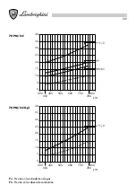
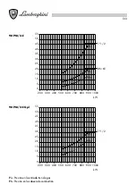
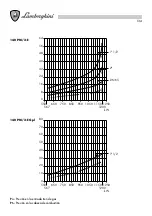
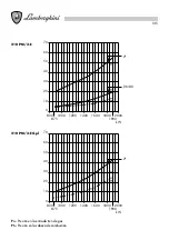
Indican la potencia en kW, en función de la contrapresión, en mbar,  en la cámara de combustión.

Presión en la cámara de combustión

Potencia térmica

kW

1800

2000

1600

1400

1200

1100

1000

900

800

700

600

500

400

300

200

150

100

55 PM/2-E

70 PM/2-E

90 PM/2-E

140 PM/2-E

210 PM/2-E

0

-0,30

-30

200

400

600

2

4

6

800

8

1000

10

1200

PA

m

b

a

r

12

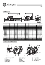
CARACTERÍSTICAS TÉCNICAS

CURVAS DE TRABAJO

55 PM/2-E

15 - 55,3

129000 - 473000

150 - 550

0.74

5

3.5

67

70 PM/2-E

24,1 - 78,8

206400 - 674240

240 - 784

0.74

5.5

4

67

90 PM/2-E

33,2 - 90,5

283800 - 774000

330 - 900

1.1

6.5

5

70

140 PM/2-E

50,2 - 120,7

430000 - 1032000

500 - 1200

1.80

9.5

6.5

70

210 PM/2-E

76 - 191

650160 - 1634000

756 - 1900

2.20

11

7.5

82

Tipo

Caudal - Potencia térmica

m

3

/h

kcal/h

kW

Motor

2P

kW

Absorción

A *

230V     400V

Peso

kg

Содержание 140 PM/2-E

Страница 1: ...FLAMMIGE GASBRENNER QUEMADORES A GAS CON DOS LLAMAS AZIENDA CERTIFICATA ISO 9001 55 70 90 140 210 PM 2 E MANUALE D INSTALLAZIONE E MANUTENZIONE INSTALLATION AND MAINTENANCE MANUAL MANUEL D INSTALLATIO...

Страница 2: ......

Страница 3: ...d de la instalaci n al uso y al mantenimiento Conserven con cuidado este folleto para cualquier ulterior consulta La instalaci n debe ser efectuada por personal t cnico cualificado que ser responsable...

Страница 4: ...ONI FIAMMA __________________________________________________ 17 COLLEGAMENTI ELETTRICI ______________________________________________ 18 POSIZIONE ELETTRODI __________________________________________...

Страница 5: ...a costruttrice utilizzando esclusivamente ricambi originali Il mancato rispetto di quanto sopra pu compromettere la sicurezza dell apparecchio Per garantire l efficienza dell apparecchio e per il suo...

Страница 6: ...disco di stabilit fiamma nella testa di combustione e causare una miscela povera aria combustibile Il bruciatore deve essere alimentato con un tipo di combustibile per il quale stato predisposto come...

Страница 7: ...e I bruciatori serie PM 2 E funzionano a due stadi con avviamento in due tempi chiusura dell aria in arresto I bruciatori sono previsti con grandezze diverse di valvole da scegliere in relazione alla...

Страница 8: ...97 M14 460 200 140 470 730 1350 140 PM 2 E 2 283 210 197 M14 460 200 140 470 750 1350 140 PM 2 E DN 80 283 210 197 M14 460 200 140 470 840 1350 90 PM 2 E DN 65 283 210 197 M14 460 200 140 470 730 1350...

Страница 9: ...00 500 400 300 200 150 100 55 PM 2 E 70 PM 2 E 90 PM 2 E 140 PM 2 E 210 PM 2 E 0 0 30 30 200 400 600 2 4 6 800 8 1000 10 1200 P A mbar 12 CARATTERISTICHE TECNICHE CURVE DI LAVORO 55 PM 2 E 15 55 3 129...

Страница 10: ...pressione gas per la misura della pressione 4 Filtro gas 5 Regolatore pressione gas 6 Organo di controllo della minima pressione gas pressostato 7 Elettrovalvola di sicurezza classe A Tempo di chiusu...

Страница 11: ...E Gpl 0 200 240 554 300 400 500 600 kW 4 8 12 16 20 24 28 0 200 240 554 300 400 500 600 kW 8 16 24 32 40 48 4 12 20 28 36 44 52 1 1 4 Pi Pt 1 1 4 Pi DN 65 Pi 1 1 2 Pi Pt Pi Pressione ingresso rampa Pt...

Страница 12: ...gresso rampa Pt Pressione alla testa 70 PM 2 E 70 PM 2 E Gpl 0 300 350 784 400 500 700 600 800 kW 10 20 30 5 15 25 35 40 0 300 350 784 400 500 700 600 800 kW 10 20 30 5 15 25 35 40 1 1 2 Pi Pt 1 1 2 P...

Страница 13: ...Pt Pressione alla testa 90 PM 2 E 90 PM 2 E Gpl 0 200 300 400 500 600 800 900 700 1000 kW 10 20 35 5 15 25 50 45 30 40 55 0 200 300 400 500 600 800 900 700 1000 kW 10 20 35 5 15 25 50 45 30 40 55 DN...

Страница 14: ...t Pressione alla testa 140 PM 2 E 140 PM 2 E Gpl 0 550 650 750 850 950 1150 1050 1250 kW 10 20 40 70 60 30 50 80 567 1200 0 550 650 750 850 950 1150 1050 1250 kW 8 16 32 56 48 24 40 64 567 1200 1 1 2...

Страница 15: ...so rampa Pt Pressione alla testa 210 PM 2 E 210 PM 2 E Gpl 0 800 1000 1200 1400 1600 1800 2000 kW 10 20 40 60 30 50 70 875 1900 0 800 1000 1200 1400 1600 1800 2000 kW 10 20 40 60 30 50 70 875 1900 2 P...

Страница 16: ...odo che il boccaglio penetri in camera di combustione secondo le in dicazioni del costruttore della caldaia stringere le viti 1 per bloccare il bruciatore 3 2 4 1 H G F 3 2 1 Modello F G H 55 PM 2 E M...

Страница 17: ...ressione in camera di combustione positiva negativa 10 20 30 40 50 60 70 80 90 100 0 200 400 600 800 1000 1200 1400 1600 1800 2000 2200 2400 2600 2800 3000 Mcal h 40 60 80 100 120 cm 140 160 180 200 2...

Страница 18: ...ECNICA ED OSSERVARE LE NORME VIGENTI I collegamenti da effettuare a cura dell installatore sono linea di alimentazione linea dei termostati TA TC TS TMF eventuale lampada di sicurezza 55 70 PM 2 E MMS...

Страница 19: ...CT Connettore controllo tenuta CT Contatto rel termico C VE PG Connettore valvola gas pressostato gas EC Elettrodo di controllo F Fusibili FA Filtro antidisturbo IG Interruttore generale Ima Interrut...

Страница 20: ...ore controllo tenuta CT Contatto rel termico C VE PG Connettore valvola gas pressostato gas EC Elettrodo di controllo F Fusibili FA Filtro antidisturbo IG Interruttore generale Ima Interruttore marcia...

Страница 21: ...e normative non esercitare sforzi meccanici sui componenti Si tenga inoltre presente la necessit degli spazi richiesti per la manutenzione del bruciatore e della caldaia N B Gli elettrodi di accension...

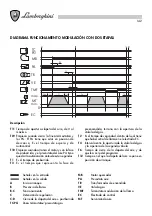
Страница 22: ...entro il quale si deve avere segnale di fiamma all elettrodo EC T4 Intervallo fra l apertura della valvola del gas e l inizio della fase di modulazione T6 Tempo di chiusura serranda aria e di azzeram...

Страница 23: ...etto alla testa di carburazione Posizionare i pomelli in corrispondenza dei valori desiderati compresi tra 1 e 3 corrispondenti rispettiva mente alla portata minima e massima del bruciatore 3 Serrare...

Страница 24: ...o Le camme si manovrano per mezzo della chiave di dotazione sono frizionate ed autobloccate Spingendo sul bottone B si disinnesta il sistema di trascinamento della serranda liberandola per spostamenti...

Страница 25: ...are in posizione di massima apertura la valvola del gas con bruciatore in funzione agire sullo stabilizzatore ove esiste fino ad ottenere la portata richiesta letta al contatore si rilevi il valore de...

Страница 26: ...sultare un valore superiore a 100 intervenire sulla regolazione della velocit dell apertura della valvola principale REGOLAZIONE PORTATA VALVOLA SKP10 12 val principale La valvola di tipo motorizzato...

Страница 27: ...iatore se la pressione del gas supera il valore prestabilito Tarare la pressione al collettore il 15 in pi della potenzialit nominale richiesta all atto dell installazione PRESSOSTATO Tipo GW 50 LGW 1...

Страница 28: ...re la posizione delle punte degli elettrodi di accensione e la posizione dell elettrodo di controllo Verificare il corretto funzionamento dei pressostati gas ed aria Con la chiusura della linea termos...

Страница 29: ...asformazione gas TRASFORMAZIONE 90 140 210 Nei modelli 90 140 210 occorre sostituire completamente il gruppo testata disponibile nell apposito kit di trasformazione Per la sostituzione del gruppo test...

Страница 30: ...rifica della combustione con rilievi di CO2 CO TF Controllo della tenuta di tutte le guarnizioni La maggior parte dei componenti sono a vista e cio immediatamente individuabili e accessibili Per acce...

Страница 31: ...l interruttore ausiliario m I morsetti 6 7 e 14 restano sotto tensione fino all eliminazione del guasto Arresto di blocco per mancanza di segnale di fiamma alla fine del primo tempo di sicurezza Arres...

Страница 32: ...ma da parte dell elettrodo di controllo a Controllare i fusibili della linea di alimentazione Controllare il fusi bili dell apparecchiatura elettrica Controllare la linea dei termostati e del pressost...

Страница 33: ...carefully as they give important safety instructions regarding installation use and maintenance Keep this manual for future reference Installation must be carried out by qualified personnel who will b...

Страница 34: ..._______________________________ 47 ELECTRICAL CONNECTIONS ____________________________________________ 48 ELECTRODES POSITION _________________________________________________ 51 GAS CONNECTION_______...

Страница 35: ...lacements exclusively Non observance of the above could compromise the safety of the appliance In order to guarantee the efficiency of the appliance and its proper operation it is indispensible to kee...

Страница 36: ...ith the type of fuel for which it was designed as indicated on the data plate and in the technical characteristics given in this manual The fuel feed line must be sealed and must be of the rigid varie...

Страница 37: ...a low excess of air leading to a high combustion efficiency and low CO and NOx emissions and consequently a low environmental impact They are suitable for pressurised and negative pressure furnaces a...

Страница 38: ...460 200 140 470 730 1350 90 PM 2 E DN 65 283 210 197 M14 460 200 140 470 760 1350 70 PM 2 E 1 1 2 283 225 180 170 M14 400 140 120 470 730 1210 70 PM 2 E 2 283 225 180 170 M14 400 140 120 470 750 1210...

Страница 39: ...300 200 150 100 55 PM 2 E 70 PM 2 E 90 PM 2 E 140 PM 2 E 210 PM 2 E 0 0 30 30 200 400 600 2 4 6 800 8 1000 10 1200 P A mbar 12 TECHNICAL CHARACTERISTICS OPERATING CURVES 55 PM 2 E 15 55 3 129000 47300...

Страница 40: ...tight at 1 bar and pressure drop 0 5 mbar 2 Vibration damping joint 3 Gas pressure tap for measuring pressure 4 Gas filter 5 Gas pressure regulator 6 Minimum gas pressure control device gas pressure s...

Страница 41: ...0 200 240 554 300 400 500 600 kW 4 8 12 16 20 24 28 0 200 240 554 300 400 500 600 kW 8 16 24 32 40 48 4 12 20 28 36 44 52 1 1 4 Pi Pt 1 1 4 Pi DN 65 Pi 1 1 2 Pi Pt Pi Pressure at gas train inlet Pt P...

Страница 42: ...Gpl 0 300 350 784 400 500 700 600 800 kW 10 20 30 5 15 25 35 40 0 300 350 784 400 500 700 600 800 kW 10 20 30 5 15 25 35 40 1 1 2 Pi Pt 1 1 2 Pi Pi 2 DN 65 Pi Pt Pi Pressure at gas train inlet Pt Pres...

Страница 43: ...0 400 500 600 800 900 700 1000 kW 10 20 35 5 15 25 50 45 30 40 55 0 200 300 400 500 600 800 900 700 1000 kW 10 20 35 5 15 25 50 45 30 40 55 DN 65 1 1 2 Pt Pi Pi 1 1 2 Pt Pi Pi Pressure at gas train in...

Страница 44: ...0 750 850 950 1150 1050 1250 kW 10 20 40 70 60 30 50 80 567 1200 0 550 650 750 850 950 1150 1050 1250 kW 8 16 32 56 48 24 40 64 567 1200 1 1 2 Pt Pi 1 1 2 2 DN 65 Pt Pi Pi Pi Pi Pressure at gas train...

Страница 45: ...l 0 800 1000 1200 1400 1600 1800 2000 kW 10 20 40 60 30 50 70 875 1900 0 800 1000 1200 1400 1600 1800 2000 kW 10 20 40 60 30 50 70 875 1900 2 Pt Pi DN 80 2 Pt Pi Pi Pi Pressure at gas train inlet Pt P...

Страница 46: ...he draught tube penetrates the combustion chamber for the length indicated by the boiler manufacturer Tighten the screws 1 to lock the burner into position 3 2 4 1 H G F 3 2 1 Model F G H 55 PM 2 E M1...

Страница 47: ...r direct reverse combustion chamber pressure positive negative 10 20 30 40 50 60 70 80 90 100 0 200 400 600 800 1000 1200 1400 1600 1800 2000 2200 2400 2600 2800 3000 Mcal h 40 60 80 100 120 cm 140 16...

Страница 48: ...ES AND OBSERVE THE REGULATIONS IN FORCE The installation technician should perform connections to the mains thermostat line TA TC TS TMF and safety light if present 55 70 PM 2 E MMS Servo control moto...

Страница 49: ...2 1 4 1 2 3 LEGEND BRM Motor relay coil C CT Connector seal check CT Thermal relay contact C VE PG Connector gas valve gas pressure EC Control electrode F Fuses FA Anti disturbance filter IG Main swit...

Страница 50: ...1 2 LEGEND BRM Motor relay coil C CT Connector seal check CT Thermal relay contact C VE PG Connector gas valve gas pressure EC Control electrode F Fuses FA Anti disturbance filter IG Main switch Ima O...

Страница 51: ...ories prescribed by regulations Do not exert mechanical force on components Also take into account the spaces required for burner and boiler maintenance N B The starting electrodes and control electro...

Страница 52: ...n which the flame signal must reach the EC electrode T4 Interval between the opening of the gas valve and the opening of the second stage T6 Air shutter closing time and program zero setting time T12...

Страница 53: ...changed in relation to the combustion head Position the knobs between 1 and 3 according to that required They correspond respectively to the minimum and maximum capacity of the burner 3 Tighten the kn...

Страница 54: ...eference disc The cams can be moved by using the equipped wrench as they are self locking By pressing button B the air flap drive system is disengaged and the air flap is free to be moved manually CAL...

Страница 55: ...eleased in 10 starts within the safety interval Ts1 is the sum of the actual safety interval in 10 starts Qn is the nominal power GAS REGULATION MAXIMUM FLOW Install a pressure gauge to measure the ga...

Страница 56: ...1 95 sec Should a value over 100 result at the end of this check regulate the opening speed of the main valve REGULATION OF VALVE SKP10 12 main valve FLOW RATE The valve is motor driven and has two op...

Страница 57: ...ner in blocking mode if the gas pressure exceeds the pre set value Set the combustion head pressure to 15 more than the nominal capacity required at the time of installation PRESSURE SWITCH Model GW 5...

Страница 58: ...he amount of gas burnt Acceptable temperature levels range between 160 and 220 C START UP Check the position of the ignition electrode tips and the position of the control electrode Check the correct...

Страница 59: ...hould purchase the suitable gas conversion kit CONVERSION 90 140 210 For models 90 140 210 the complete head set must be replaced this is available in a conversion kit To replace the head set see Main...

Страница 60: ...ir pressure switches check combustion taking readings of CO2 and CO emissions and of flue gas temperature check all seals The majority of components are visible and immediately accessible To access th...

Страница 61: ...itch m Terminals 6 7 and 14 remain under voltage until the fault has been corrected Lockout because no flame signal is present after completion of the 1st safety time Lockout because no flame signal h...

Страница 62: ...es not give its enabling signal a the control electrode either fails to detect the presence of the flame or it does so inadequately a check the mains fuses and the control box fuses Check the thermost...

Страница 63: ...issent des indications importantes pour la s curit de l installation de l emploi et de la manutention Conserver avec soin ce livret pour ult rieures consultations L installation doit tre effectu e par...

Страница 64: ...____ 76 DIMENSIONS DE LA FLAMME_____________________________________________ 77 BRANCHEMENTS ELECTRIQUES ___________________________________________ 78 POSITION ELECTRODES ____________________________...

Страница 65: ...ant exclusivement des pi ces d tach es d origine Le non respect de ces r gles peut compromettre la s curit de l appareil Pour garantir les performances et le bon fonctionnement de l appareil il est in...

Страница 66: ...ion de la flamme dans la t te de combustion et provoquer la formation d un m lange air combustible pauvre Le br leur doit tre aliment par le type de combustible pr vu d apr s les indications figurant...

Страница 67: ...n permet l utilisation de tous les gaz naturels m lang s et liquides contacter le service technique pour des informations sp cifiques le m lange intime gaz air permet d obtenir des combustions faible...

Страница 68: ...4 460 200 140 470 730 1350 140 PM 2 E 2 283 210 197 M14 460 200 140 470 750 1350 140 PM 2 E DN 80 283 210 197 M14 460 200 140 470 840 1350 90 PM 2 E DN 65 283 210 197 M14 460 200 140 470 730 1350 90 P...

Страница 69: ...00 700 600 500 400 300 200 150 100 55 PM 2 E 70 PM 2 E 90 PM 2 E 140 PM 2 E 210 PM 2 E 0 0 30 30 200 400 600 2 4 6 800 8 1000 10 1200 P A mbar 12 CARACTERISTIQUES TECHNIQUES COURBES DE TRAVAIL 55 PM 2...

Страница 70: ...nt anti vibrant version ITALIA 3 Prise de pression gaz pour la mesure de la pression 4 Filtre gaz 5 R gulateur de pression gaz 6 Organe de contr le de la pression minimum gaz pressostat 7 Electrovanne...

Страница 71: ...l 0 200 240 554 300 400 500 600 kW 4 8 12 16 20 24 28 0 200 240 554 300 400 500 600 kW 8 16 24 32 40 48 4 12 20 28 36 44 52 1 1 4 Pi Pt 1 1 4 Pi DN 65 Pi 1 1 2 Pi Pt Pi Pression l entr e de la rampe P...

Страница 72: ...Gpl 0 300 350 784 400 500 700 600 800 kW 10 20 30 5 15 25 35 40 0 300 350 784 400 500 700 600 800 kW 10 20 30 5 15 25 35 40 1 1 2 Pi Pt 1 1 2 Pi Pi 2 DN 65 Pi Pt Pi Pression l entr e de la rampe Pt P...

Страница 73: ...300 400 500 600 800 900 700 1000 kW 10 20 35 5 15 25 50 45 30 40 55 0 200 300 400 500 600 800 900 700 1000 kW 10 20 35 5 15 25 50 45 30 40 55 DN 65 1 1 2 Pt Pi Pi 1 1 2 Pt Pi Pi Pression l entr e de l...

Страница 74: ...650 750 850 950 1150 1050 1250 kW 10 20 40 70 60 30 50 80 567 1200 0 550 650 750 850 950 1150 1050 1250 kW 8 16 32 56 48 24 40 64 567 1200 1 1 2 Pt Pi 1 1 2 2 DN 65 Pt Pi Pi Pi Pi Pression l entr e de...

Страница 75: ...Gpl 0 800 1000 1200 1400 1600 1800 2000 kW 10 20 40 60 30 50 70 875 1900 0 800 1000 1200 1400 1600 1800 2000 kW 10 20 40 60 30 50 70 875 1900 2 Pt Pi DN 80 2 Pt Pi Pi Pi Pression l entr e de la rampe...

Страница 76: ...ue l embout p n tre dans la chambre de combustion selon les indications du fabricant de la chaudi re serrer les vis 1 pour bloquer le br leur 3 2 4 1 H G F 3 2 1 Modele F G H 55 PM 2 E M14 180 225 283...

Страница 77: ...pression l int rieur de la chambre de combustion positive n gative 10 20 30 40 50 60 70 80 90 100 0 200 400 600 800 1000 1200 1400 1600 1800 2000 2200 2400 2600 2800 3000 Mcal h 40 60 80 100 120 cm 14...

Страница 78: ...ET OBSERVER LES NORMES EN VIGUEUR Les branchements effectuer par l installateur sont les suivants ligne d alimentation ligne des thermostats TA TC TS TMF ventuel voyant de s curit 55 70 PM 2 E MMS Bo...

Страница 79: ...ais moteur C CT Connecteur c ntrole tanch it CT Contact relais termique C VE PG Connecteur vanne gaz pressostat gaz EC Electrode de contr le F Fusibles FA Filtre antiparasite IG Interrupteur principal...

Страница 80: ...C CT Connecteur c ntrole tanch it CT Contact relais termique C VE PG Connecteur vanne gaz pressostat gaz EC Electrode de contr le F Fusibles FA Filtre antiparasite IG Interrupteur principal Ima Interr...

Страница 81: ...res prescrits par les normes ne pas exercer d efforts m caniques sur les composants Tenir compte des espaces n cessaires pour l entretien du br leur et de la chaudi re N B Les lectrodes d allumage et...

Страница 82: ...de s curit au cours duquel le signal de flamme doit arriver l lectrode EC T4 Intervalle de temps entre l ouverture de la van ne du gaz et l ouverture de la seconde allure T6 Temps de fermeture du clap...

Страница 83: ...sition de l embout par rapport la t te de combustion Positionner les pommeaux en face des valeurs d sir es de 1 3 correspondant respectivement la puissance minimum et maximum du br leur 3 Une fois le...

Страница 84: ...rep re Pour manoeuvrer les cames qui sont auto bloqu es utiliser la cl en dotation En poussant sur le bouton B le syst me d entra nement du volet se d senclenche et les d placements manuels sont poss...

Страница 85: ...ur placer la vanne de gaz en position d ouverture maximum lorsque le br leur est en fonction agir sur le stabilisateur si pr sent jusqu l obtention du d bit d sir indiqu sur le compteur v rifier la va...

Страница 86: ...p rieure 100 il est n cessaire d intervenir au niveau du r glage de la vitesse de l ouverture de la vanne principale REGLAGE DEBIT VANNE SKP10 12 vanne principale La vanne est de type motoris e deux p...

Страница 87: ...ur lorsque la pression de gaz d passe la valeur pr r gl e Tarer la pression la t te de combustion de 15 en plus par rapport la puissance nominale demand e au moment de l installation PRESSOSTAT Type G...

Страница 88: ...ses entre 160 C et 220 C MISE EN SERVICE V rifier la position des pointes des lectrodes d allumage et la position de l lectrode de contr le V rifier le bon fonctionnement des pressostats du gaz et de...

Страница 89: ...que permettant ce passage TRANSFORMATION 90 140 210 Pour les mod les 90 140 210 il faut remplacer enti rement le groupe t te qui se trouve dans le kit sp cifique de transformation Pour remplacer le gr...

Страница 90: ...gaz Contr le de la combustion avec mesures du CO2 CO TEMPERATURE DES FUMEES Contr le de l tanch it de tous les joints La plupart des composants sont visibles c est dire imm diatement rep rables et acc...

Страница 91: ...interrupteur auxiliaire m Les bornes 6 7 et 14 restent sous tension jusqu limination du d faut Mise en s curit due l absence de signal de flamme au terme du premier temps de s curit Mise en s curit ca...

Страница 92: ...se d tection de la flamme par l lectrode de contr le a Contr ler les fusibles de la ligne d alimentation contr ler le fusible de la bo te de contr le Contr ler la ligne des thermostats et du pressosta...

Страница 93: ...inweise f r eine sichere Installation Wartung und einen sicheren Betrieb liefern Bewahren Sie dieses Handbuch f r sp tere Verwendung sorgf ltig auf Die Installation mu von Fachpersonal ausgef hrt werd...

Страница 94: ...06 FLAMMENDIMENSION _________________________________________________107 ELEKTRISCHE VERDRAHTUNG ___________________________________________108 POSITION DER ELEKTRODEN ________________________________...

Страница 95: ...darf nur von einem durch die Herstellerfirma autorisierten Vertragskundendienst unter Verwendung von Originalersatzteilen erfolgen Die Nichteinhaltung dieser Vorschrift kann die Sicherheit des Ger ts...

Страница 96: ...ammenstabilit t im Brennerkopf ansammeln und ein mageres Gas Luft Gemisch bilden Der Brenner mu mit dem f r ihn vorgesehenen Brennstoff versorgt werden wie dies auf der Kenndatentafel und in den techn...

Страница 97: ...s erlaubt den Einsatz von allen nat rlichen Gasen Mischgasen und Fl ssiggasen f r weitere Informationen wenden Sie sich bitte an den technischen Kundendienst durch die feine Durchmischung von Gas Luft...

Страница 98: ...97 M14 460 200 140 470 730 1350 140 PM 2 E 2 283 210 197 M14 460 200 140 470 750 1350 140 PM 2 E DN 80 283 210 197 M14 460 200 140 470 840 1350 90 PM 2 E DN 65 283 210 197 M14 460 200 140 470 730 1350...

Страница 99: ...00 600 500 400 300 200 150 100 55 PM 2 E 70 PM 2 E 90 PM 2 E 140 PM 2 E 210 PM 2 E 0 0 30 30 200 400 600 2 4 6 800 8 1000 10 1200 P A mbar 12 TECHNISCHE DATEN ARBEITSKURVEN 55 PM 2 E 15 55 3 129000 47...

Страница 100: ...Dichtheitsgarantie bei 1 bar und Druckverlust 0 5 mbar 2 Vibrationsschutz Version ITALIA 3 Druckme stutzen f r Gas 4 Gasfilter 5 Gasdruckregler 6 Kontrollorgan f r den min Gasdruck Druckw chter 7 Sich...

Страница 101: ...E Gpl 0 200 240 554 300 400 500 600 kW 4 8 12 16 20 24 28 0 200 240 554 300 400 500 600 kW 8 16 24 32 40 48 4 12 20 28 36 44 52 1 1 4 Pi Pt 1 1 4 Pi DN 65 Pi 1 1 2 Pi Pt Pi Druck am Eingang der Rampe...

Страница 102: ...2 E Gpl 0 300 350 784 400 500 700 600 800 kW 10 20 30 5 15 25 35 40 0 300 350 784 400 500 700 600 800 kW 10 20 30 5 15 25 35 40 1 1 2 Pi Pt 1 1 2 Pi Pi 2 DN 65 Pi Pt Pi Druck am Eingang der Rampe Pt...

Страница 103: ...200 300 400 500 600 800 900 700 1000 kW 10 20 35 5 15 25 50 45 30 40 55 0 200 300 400 500 600 800 900 700 1000 kW 10 20 35 5 15 25 50 45 30 40 55 DN 65 1 1 2 Pt Pi Pi 1 1 2 Pt Pi Pi Druck am Eingang d...

Страница 104: ...550 650 750 850 950 1150 1050 1250 kW 10 20 40 70 60 30 50 80 567 1200 0 550 650 750 850 950 1150 1050 1250 kW 8 16 32 56 48 24 40 64 567 1200 1 1 2 Pt Pi 1 1 2 2 DN 65 Pt Pi Pi Pi Pi Druck am Eingang...

Страница 105: ...2 E Gpl 0 800 1000 1200 1400 1600 1800 2000 kW 10 20 40 60 30 50 70 875 1900 0 800 1000 1200 1400 1600 1800 2000 kW 10 20 40 60 30 50 70 875 1900 2 Pt Pi DN 80 2 Pt Pi Pi Pi Druck am Eingang der Rampe...

Страница 106: ...nsch schieben da der Brennerkopf in der vom Hersteller geforderten L nge in den Verbrennungsraum ragt die Schrauben 1 zur Befestigung des Brenners festziehen 3 2 4 1 H G F 3 2 1 Modell F G H 55 PM 2 E...

Страница 107: ...k im Feurraum berdruck Unterdruck 10 20 30 40 50 60 70 80 90 100 0 200 400 600 800 1000 1200 1400 1600 1800 2000 2200 2400 2600 2800 3000 Mcal h 40 60 80 100 120 cm 140 160 180 200 220 240 260 280 300...

Страница 108: ...ND BEACHTEN SIE DIE GELTENDEN VORSCHRIFTEN Vom Installateur sind folgende Verdrahtungen auszuf hren Versorgungsleitung Leitung f r die Temperaturw chter TA TC TS TMF eventuelle Sicherheitslampe 55 70...

Страница 109: ...2 1 4 1 2 3 ZEICHENERKL RUNG BRM Relaisspule Motor C CT Stecher dichtheitskontrolle CT Kontakt thermorel C VE PG Stecker gasventil gasdruckw chter EC Kontrollelektrode F Sicherungen FA Entst rkondens...

Страница 110: ...ZEICHENERKL RUNG BRM Relaisspule Motor C CT Stecher dichtheitskontrolle CT Kontakt thermorel C VE PG Stecker gasventil gasdruckw chter EC Kontrollelektrode F Sicherungen FA Entst rkondensator IG Haup...

Страница 111: ...teile darf keine mechanische Beanspruchung ausge bt werden Au erdem ist darauf zu achten da der f r die Wartungsarbeiten von Brenner und Kessel ben tigte Platzbedarf gew hrleistet ist Hinweis Die Z nd...

Страница 112: ...mu die berwachungselektrode EC das Flammensignal erhalten T4 Intervall zwischen der ffnung des Gasventils und der ffnung der zweiten Stufe T6 Schlie zeit der Luftklappe und R cksetzen des Programms T...

Страница 113: ...Kn pfe kann die Stellung der Brennerm ndung zum Verbrennungskopf ver ndert werden Die Kn pfe entsprechend der gew nschten Klein und Vollastwerte des Brenners zwischen 1 und 3 einstellen 3 Die Kn pfe...

Страница 114: ...mit dem beiliegenden Schl ssel einstellen sie sind mit Kupplung versehen und selbstblockierend Durch Dr cken auf Knopf B wird das Schleppsystem der Luftklappe ausgekoppelt und manuelle Verschiebungen...

Страница 115: ...Gasventil auf gr te ffnung stellen Brenner starten und den Duckregler wo vorhanden so lange bet tigen bis der gew nschte Durchsatz erreicht ist abgelesen auf dem Gasz hler nun den Druck am Manometer...

Страница 116: ...trolle h her als 100 sein sollte mu die ffnungsgeschwindigkeit des Hauptventils nachgestellt werden EINSTELLUNG DER DURCHFLUSSMENGE AM VENTIL SKP10 12 Hauptventil Das Ventil ist elektrisch betrieben u...

Страница 117: ...w chter f r den max Druck hat die Aufgabe den Brenner zu verriegeln wenn der Gasdruck den eingestellten Wert berschreitet Der Gasdruck am Brennerrohr mu um 15 h her eingestellt werden als die bei der...

Страница 118: ...en zwischen 160 C und 220 C INBETRIEBNAHME Die Positionen der Z ndelektrodenspitzen und die Position der berwachungselektrode berpr fen Die einwandfreie Funktion der Gas und Luftdruckw chter berpr fen...

Страница 119: ...ellsatz gekauft werden UMSTELLUNG 90 140 210 Bei den Modellen 90 140 210 muss die Kopfgruppe komplett durch die im entsprechenden Umstellsatz be findliche ersetzt werden F r die Auswechslung der Kopfg...

Страница 120: ...rbrennung mit Messung von CO 2 CO Abgastemperatur Dichtheitskontrolle aller Dichtungen Der Gro teil der Bauteile ist frei sichtbar daher leicht erkennbar und zug nglich Der Zugang in den Brennerkopf i...

Страница 121: ...ie St rung behoben ist Blockierung da nach Ablauf der ersten Sicherheitsfrist kein Flammensignal vorhanden ist Blockierung da nach Ablauf der zweiten Sicherheitsfrist kein Flammensignal erfa t worden...

Страница 122: ...lende oder unzureichende Flammenerkennung der Ionisationselektrode a icherungen in der elektr Versorgungsleitung berpr fen Sicherungen am Feuerungsautomat berpr fen Versorgungsleitung der Thermostat u...

Страница 123: ...dicaciones importantes relativas a la seguridad de la instalaci n al uso y al mantenimiento Conserven con cuidado este folleto para cualquier ulterior consulta La instalaci n debe ser efectuada por pe...

Страница 124: ..._________________________________________________ 128 COMPONENTES PRINCIPALES __________________________________________ 128 CARACTER STICAS T CNICAS __________________________________________ 129 CUR...

Страница 125: ...utilizando nicamente repuestos originales El no respetar todo lo que acabamos de mencionar puede comprometer la seguridad del aparato Para garantizar la eficacia de la caldera y para su correcto func...

Страница 126: ...de llama en la cabeza de combusti n y causar una mezcla pobre de aire combustible El quemador hay que alimentarlo con el tipo de combustible para el que se ha preparado como indican la chapa con los...

Страница 127: ...con caudal reducido La conformaci n de la cabeza de combusti n permite usar todo tipo de gas natural mezclados y l quidos consulte con el servicio t cnico para informaciones concretas la ntima mezcla...

Страница 128: ...40 470 730 1350 140 PM 2 E 1 1 2 283 210 197 M14 460 200 140 470 730 1350 140 PM 2 E 2 283 210 197 M14 460 200 140 470 750 1350 140 PM 2 E DN 80 283 210 197 M14 460 200 140 470 840 1350 90 PM 2 E DN 6...

Страница 129: ...600 500 400 300 200 150 100 55 PM 2 E 70 PM 2 E 90 PM 2 E 140 PM 2 E 210 PM 2 E 0 0 30 30 200 400 600 2 4 6 800 8 1000 10 1200 P A mbar 12 CARACTER STICAS T CNICAS CURVAS DE TRABAJO 55 PM 2 E 15 55 3...

Страница 130: ...nte 3 Toma de presi n gas para medir la presi n 4 Filtro gas 5 Regulador de presi n gas 6 rgano de control de la presi n m nima de gas pres stato 7 Electrov lvula de seguridad clase A Tiempo de cierre...

Страница 131: ...240 554 300 400 500 600 kW 4 8 12 16 20 24 28 0 200 240 554 300 400 500 600 kW 8 16 24 32 40 48 4 12 20 28 36 44 52 1 1 4 Pi Pt 1 1 4 Pi DN 65 Pi 1 1 2 Pi Pt Pi Presi n en la entrada tren de gas Pt P...

Страница 132: ...300 350 784 400 500 700 600 800 kW 10 20 30 5 15 25 35 40 0 300 350 784 400 500 700 600 800 kW 10 20 30 5 15 25 35 40 1 1 2 Pi Pt 1 1 2 Pi Pi 2 DN 65 Pi Pt Pi Presi n en la entrada tren de gas Pt Pres...

Страница 133: ...500 600 800 900 700 1000 kW 10 20 35 5 15 25 50 45 30 40 55 0 200 300 400 500 600 800 900 700 1000 kW 10 20 35 5 15 25 50 45 30 40 55 DN 65 1 1 2 Pt Pi Pi 1 1 2 Pt Pi Pi Presi n en la entrada tren de...

Страница 134: ...850 950 1150 1050 1250 kW 10 20 40 70 60 30 50 80 567 1200 0 550 650 750 850 950 1150 1050 1250 kW 8 16 32 56 48 24 40 64 567 1200 1 1 2 Pt Pi 1 1 2 2 DN 65 Pt Pi Pi Pi Pi Presi n en la entrada tren d...

Страница 135: ...0 1000 1200 1400 1600 1800 2000 kW 10 20 40 60 30 50 70 875 1900 0 800 1000 1200 1400 1600 1800 2000 kW 10 20 40 60 30 50 70 875 1900 2 Pt Pi DN 80 2 Pt Pi Pi Pi Presi n en la entrada tren de gas Pt P...

Страница 136: ...ue la boca de fuego penetre en la c mara de combusti n seg n las indicaciones del fabricante de la caldera apretar los tornillos 1 para bloquear el quemador 3 2 4 1 H G F 3 2 1 Modelo F G H 55 PM 2 E...

Страница 137: ...nversi n la presi n en la c mara de combusti n positiva negativa 10 20 30 40 50 60 70 80 90 100 0 200 400 600 800 1000 1200 1400 1600 1800 2000 2200 2400 2600 2800 3000 Mcal h 40 60 80 100 120 cm 140...

Страница 138: ...Y OBSERVE LAS NORMAS VIGENTES Las conexiones que tiene efectuar el instalador son la l nea de alimentaci n la l nea de los termostatos TA TC TS TMF y la l mpara de seguridad en caso de que exista 55...

Страница 139: ...trol de estanqueidad CT Contacto rel termico C VE PG Conector valvula gas pres stato gas EC Electrodo de control F Fusibles FA Filtro antiparasitario IG Interruptor general Ima Interruptor encendido a...

Страница 140: ...ueidad CT Contacto rel termico C VE PG Conector valvula gas pres stato gas EC Electrodo de control F Fusibles FA Filtro antiparasitario IG Interruptor general Ima Interruptor encendido apagado LF L mp...

Страница 141: ...normativas no ejerza esfuerzos mec nicos sobre los componentes Tenga tambi n en cuenta que hay que dejar el espacio necesario para poder realizar el mantenimiento del quemador y de la caldera Nota Los...

Страница 142: ...m ximo TW Empieza cuando cierra la l nea termost tica y los PG El PA tiene que estar en posici n de descanso Es el tiempo de espera y de autocontrol T10 Empieza cuando arranca el motor y con la fase...

Страница 143: ...cabeza de combusti n Coloque las tuercas de manera que correspondan con los valores deseados comprendidos entre 1 y 3 que corresponden respectivamente a la potencia m nima y m xima del quemador 3 Apr...

Страница 144: ...nipulan mediante la llave que se da con el equipamiento se mueven con un poco de roce y son autobloqueantes Presionando el bot n B se desconecta el sistema de arrastre del cierre del aire dej ndolo li...

Страница 145: ...a la v lvula del gas con el quemador en funcionamiento actuar con el estabilizador si lo hubiera hasta que se obtenga el caudal requerido le do en el contador y hay que ver el valor de la presi n en e...

Страница 146: ...superior a 100 regule la velocidad de la apertura de la v lvula principal REGULACI N DEL CAUDAL DE LA V LVULA SKP10 12 v lv principal La v lvula es motorizada y tiene dos posiciones de apertura accion...

Страница 147: ...de bloquear el quemador si la presi n del gas supera el valor preestablecido Regule la presi n en la cabeza de combusti n un 15 m s de la capacidad de potencia nominal requerida en el momento de la in...

Страница 148: ...C y 220 C PUESTA EN FUNCIONAMIENTO Controlen la posici n de las puntas de los electrodos de encendido y de la del electrodo de control Controlen el perfecto funcionamiento de los presostatos del gas y...

Страница 149: ...kit de transformaci n de gas a tal efecto TRANSFORMACI N 90 140 210 En los modelos 90 140 210 hay que sustituir completamente el grupo de la cabeza disponible en el kit de transformaci n a tal efecto...

Страница 150: ...n detecciones de CO2 CO temperatura humos Control de la estanqueidad de todas las empaquetaduras La mayor a de los componentes est n a la vista lo que los hacen inmediatamente indibiduables y accesibl...

Страница 151: ...borne 8 por el interruptor auxiliar m Los bornes 6 7 y 14 permanecen bajo tensi n hasta que se soluciona la aver a Parada de bloqueo por falta de se al de llama al final del primer tiempo de segurida...

Страница 152: ...tecci n de la llama por par te del electrodo de control a Controlar los fusibles de la l nea de alimentaci n controlar el fusible de la caja de control Controlar la l nea de los termostatos y del pres...

Страница 153: ...153...

Страница 154: ...154...

Страница 155: ......

Страница 156: ...E IN ACCIAIO GENERATORI DI ARIA CALDA TRATTAMENTO ACQUA CONDIZIONAMENTO 08 2006 Cod 97 00286 0 1 LAMBORGHINI CALOR S p A VIA STATALE 342 44040 DOSSO FERRARA ITALIA TEL ITALIA 0532 359811 EXPORT 0532 3...

Отзывы: