115
|
www.lakeshore.com
4. If you do not have a planarization assembly, loosen the M4 screw that holds the
stabilization bracket to the probe arm base.
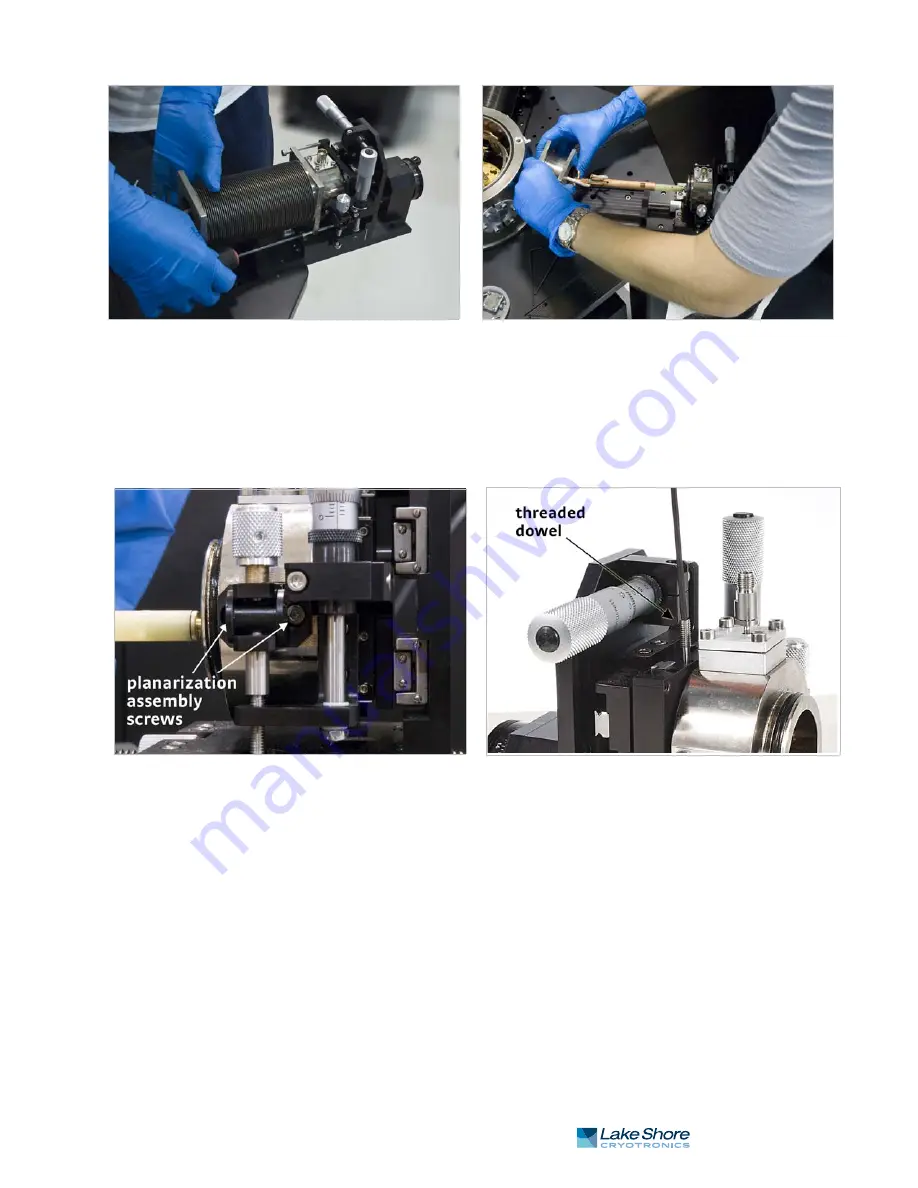
5. If you have a planarization assembly attached to the probe arm, loosen the two
M3 screws that hold the planarization assembly to the arm base. You may need
to turn the z-axis micrometer to access the screw that is behind the micrometer
(FIGURE 5-13). The planarization assembly will remain attached to the stage.
The probe arm base is loosely secured to the z-axis stage with two stainless steel
threaded dowels. Unscrew the threaded dowels, and then pull both dowels out
(FIGURE 5-13). Access to the threaded dowels may be to the side of the z-axis
stage as shown in FIGURE 5-13 or to the top of the z-axis stage.
6. Lift the probe arm and base off the z-axis stage. Pull the probe arm and base out
of the stage.
FIGURE 5-12
Left: Remove the four horizontal screws that attach the bellows to the z-axis stage;
Right: Compress the bellows to remove it from the probe arm
FIGURE 5-13
Left: Loosen the two screws holding the planarization assembly to the probe arm base; Right: Pull out the threaded dowels
Содержание CRX-6.5K
Страница 4: ...Model CRX 6 5K Probe Station ...
Страница 52: ...42 CHAPTER 2 System Overview Model CRX 6 5K Probe Station ...
Страница 92: ...82 CHAPTER 3 Installation and Setup Model CRX 6 5K Probe Station ...
Страница 162: ...152 CHAPTER 6 Maintenance and Troubleshooting Model CRX 6 5K Probe Station ...
Страница 166: ...156 INDEX Model CRX 6 5K Probe Station ...


