Pinnacle
TM
100 Modem
Hosted Mode Low Power User Guide
https://www.lairdconnect.com/
6
© Copyright 2020 Laird. All Rights Reserved
Americas
: +1-800-492-2320
Europe
: +44-1628-858-940
Hong Kong
: +852 2923 0610
2.4
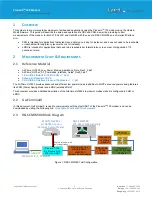
Amarisoft Block Diagram
Antenna
2 U x ½ wi d th S o ft F ra me
S tac ka b le
( p
l ace over ins tr ument, t he
n Send t o Back)
12.34 56
1.234 56
V1
On/ Off
7
8
9
4
5
6
1
2
3
.
0
-
< >
+V2
Gnd
DC P owe r Sup p ly
Vol ts
Am ps
Com
-V3
+V1
Pinnacle
TM
100
On Pinnacle DVK
LTE U.FL CON1
*Replace J4 Jumper with
power supply leads
USB VCP
115200, N, 8, 1, RTS/CRTS
Antenna
Amarisoft Callbox mini
Figure 2: Amarisoft Test Configuration
2.5
DVK Setup
Setup the DVK’s IO switches as shown in Figure 3. Place a Jumper Wire on IO M2.59 and connect to J9 Pin 11 (1.8V). The
N6705C DC Power Analyzer setup as the Current Meter is connect using J4.
Figure 3: DVK Configuration


