Operation Manual
Liquid-Air Cooling Unit LA 5000
Version 1.0
Страница 1: ...Operation Manual Liquid Air Cooling Unit LA 5000 Version 1 0 ...
Страница 2: ...utilization or posting of its contents is not permitted unless formally granted Violations entail claims for compensation All copyrights including rights due to patent grant or registration of a utility model or design are reserved All product names used in this manual are trademarks of the corresponding manufacturers Technical modifications are subject to change ...
Страница 3: ...revent Hazards 10 3 3 2 Hints Regarding the Electrical Equipment 10 3 3 3 Environmental Issues 11 3 4 Safety Equipment 11 3 4 1 Safety and Signalling Equipment included in the Unit 11 3 4 2 Guards 12 3 4 3 Caution Labels 12 3 5 In Case of Accidents 13 4 Product Description 14 4 1 Intended Use 14 4 2 Use not in Conformance with the Intended Use 14 4 3 Unit Components 15 4 4 Specifications 16 4 5 Se...
Страница 4: ... work after Storage 23 7 Controlling the Unit 24 7 1 Safety Indications for Controlling the Unit 24 7 2 Switching on the Unit 24 7 3 Switching off the Unit 24 7 4 Settings 25 8 Disruptions 27 8 1 Disruption in Operation 27 8 1 1 Trouble Shooting 27 9 Maintenance and Cleaning 28 9 1 Maintenance Schedule 28 9 2 Cleaning of Heat Exchanger 28 9 3 Refilling of Coolant 28 9 4 Cleaning of Strainer 29 9 5...
Страница 5: ...AL SYSTEMS 34 12 Wear Parts and Spare Parts 35 12 1 Units wear and spare parts 35 Addendum 37 Flow scheme 37 Wiring diagram 38 Dimensional drawing 39 Performance diagram 40 Flow versus pressure 41 EC DECLARTION OF CONFORMITY Fel Bokmärket är inte definierat History of Changes Document No 387009851 Date Index Reason for Change Name Page 09 August 2022 V 1 0 Document number changed from 337007274 to...
Страница 6: ...peration repair or maintenance of the product by people that are not fully authorized Use of the product despite of defect wrongly implemented or non functional safety units or protective gear Unauthorized or forbidden modifications by the user concerning the electrical equipment of the unit Unauthorized or forbidden modifications by the user concerning the mechanical structure of the unit Unautho...
Страница 7: ...his unit please use the contact information given below Always communicate the following Your name and address Name of contact at your address Product data as on identification plate Type of unit serial number and year of manufacture Company contact Post Laird Thermal Systems s r o Prumyslová 497 462 11 Liberec Czech Republic Tel 420 488 575 111 Fax 420 488 575 303 E Mail info lcs lairdthermal com...
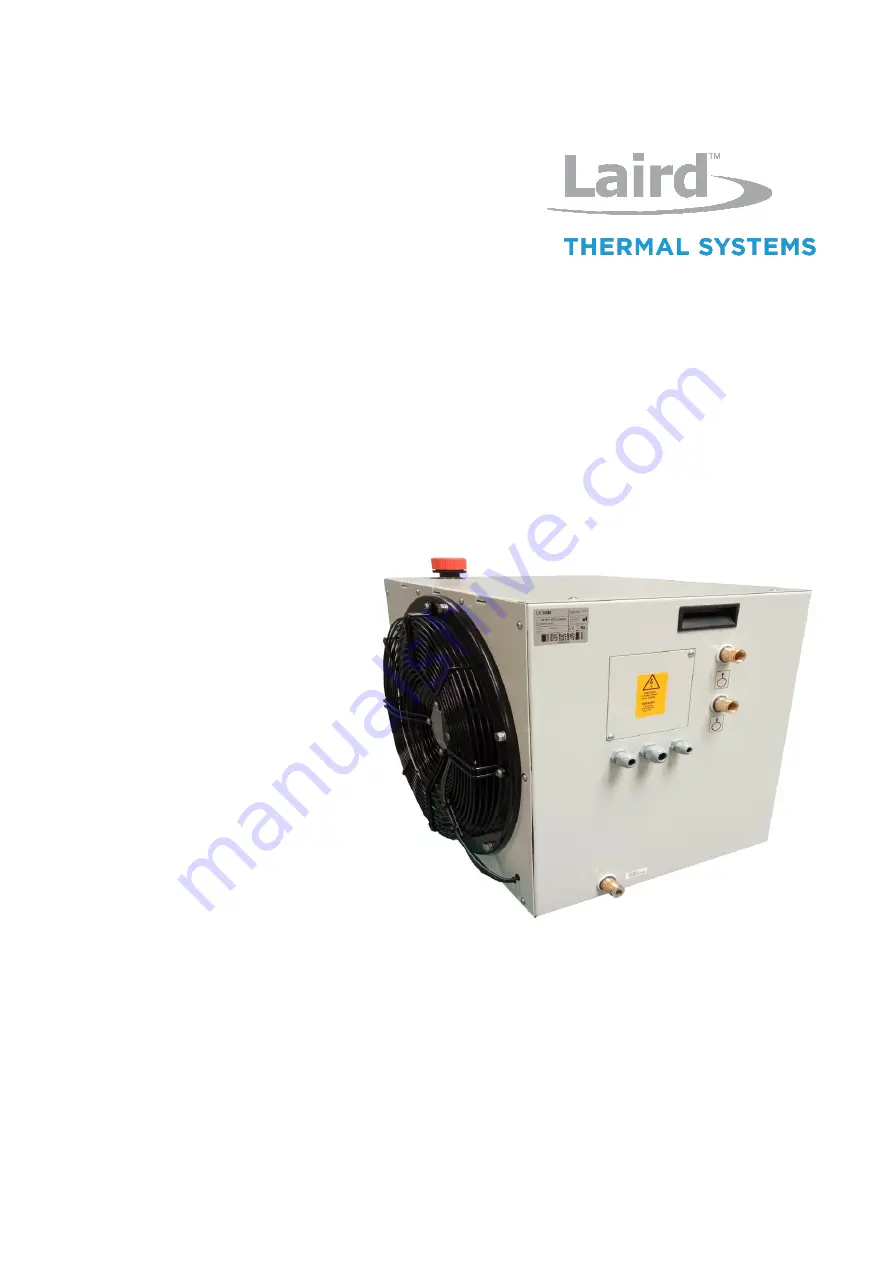
Страница 8: ...hermal Systems s r o Type of product Liquid air cooler Type of unit LA 5000 Article number 387009381 Table 1 Unit specifications 2 2 Identification Plate The identification plate is attached to the front side of the unit see Fig 1 Fig 1 Position of identification plate 1 Identification plate Fig 2 Unit specific identification plate 1 Unit type 2 Article number 3 Serial number 4 Electrical specific...
Страница 9: ...ossible damage to property Inobservance may lead to reversible injuries or to damage to property 3 2 Safety Symbols In this Operation Manual concrete safety instructions are given in order to point out unpreventable residual risks when operating the unit These risks include danger for Human beings The unit and other equipment The environment The safety symbols used in this manual are indicated bel...
Страница 10: ...rning the unit should be reported to the responsible person Stick to the accident prevention regulations as well as any regional regulations Unit must be unplugged from mains before it is opened 3 3 2 Hints Regarding the Electrical Equipment DANGER Danger to life through electrical shock when working on the electrical equipment of the unit Switch off the unit before starting your work Disconnect t...
Страница 11: ...tegrated in the local control environment by the customer unless otherwise noted These works must be carried out only by trained experts All required information can be taken from the wiring diagram shown in the addendum Safety equipment must not be modified removed or taken out of operation All parts of the safety equipment must be accessible at all times 3 4 1 Safety and Signalling Equipment inc...
Страница 12: ...emoved independently from the main cover by opening 7 screws The unit cover is fixed by 7 screws The electrical terminal area is accessable after removing the corresponding plate on the front side held by two screws For unscrewing screwing or opening closing of the fasteners a 7 0 x 1 0 mm slotted screwdriver is required Fig 4 Guards 1 Unit cover 2 Access plate for electric terminal block 3 Remova...
Страница 13: ...22 Version 1 0 Liquid Air Cooling Unit LA 5000 387009381 Fig 5 Caution labels on the unit 1 Hint on electrical hazardous area behind access plate 3 5 In Case of Accidents Should you or another person be injured when working with the unit Stay calm Render first aid Call the company first aider without exception 1 ...
Страница 14: ...oper operational conditions is not allowed since otherwise the operation safety can not be granted When using the unit in a way not compliant with the intended use hazardous situations may occur Operation of the unit is not allowed under the following conditions The unit is used for a purpose other than the one it is intended for The unit or parts of it are damaged the electrical installation is n...
Страница 15: ...for coolant 3 Pump 4 Casing Cooling Circuit In the cooling circuit the coolant is driven by the pump to the device that is to be cooled and back via the return flow The heat is dissipated into the ambient air by an air cooled heat exchanger Exceedance of the maximum pump pressure is prevented by a by pass circuit The liquid temperature is controlled by an electric thermostat whereas liquid through...
Страница 16: ...Noise level 1m 57dB A 50Hz Table 5 Performance data Environmental conditions Operating temperature 5 C 50 C Water Operating temperature 10 C 50 C Water 70 Glycol 30 Operating relative humidity 20 80 Storage temperature 25 C 70 C Empty Storage relative humidity 10 95 Table 6 Environmental conditions Settings Flow control device 4 0 0 1 lpm opening threshold Thermal switch 55 C 5 C tolerance 15 C hy...
Страница 17: ...alled without sharp bends 4 5 2 Environmental Conditions CAUTION Risk of damage through unsuitable environmental conditions Damage to property and corrosion damage may result and are not covered by manufacturer s liability The unit is only authorized for use in indoor environments The unit must not be stored or operated in agressive humid environments The unit must not be stored or operated outdoo...
Страница 18: ...ft 5 2 Transportation of the Unit The unit is delivered shrinked in foil on a transportable pallet Leave the unit on the pallet until bringing it into service Use a forklift or jack lift for transportation to the installation location 5 3 Unpacking Remove the foil before setting up the unit Inspect the unit with regards to Damage caused by transportation Completeness of delivery Lift the unit with...
Страница 19: ...hapter Safety Regulations on page 9 6 2 Setting to Work 6 2 1 Placement Fig 7 Minimum clearance for air entrance and air exit 1 Ventilation grid 1 Move the unit to its installation location as mentioned in chapter 5 2 2 Place the unit in a way that air entrance and air exit are not obstructed Wall clearance must not be less than 0 5 m otherwise cooling capacity may be restricted Unit should not be...
Страница 20: ...are connected to the unit by means of hose nipples Liquid outlet and liquid inlet are indicated with respective symbols Fig 8 Labeling of liquid inlet and liquid outlet 1 Connect a suitable hose to the hose nipples for liquid inlet and liquid outlet and secure it with a clamp respectively 2 Connect the hoses to the corresponding nipples of the device to be cooled PLEASE NOTE When connecting the co...
Страница 21: ...e installation is dead volt free Carry out earthing or short circuiting CAUTION Risk of damage through improper connections Improper integration of the unit into the safety circuit of the device to be cooled will lead to the inoperativeness of the safety equipment listed in chapter 3 4 1 on page 11 All connections required must be incorporated according to the wiring diagram shown in the addendum ...
Страница 22: ...eed the mains cable through one of the cable bushings and make the connection to the terminal Then do the same with the wires for the implementation of the safety circuit 3 Remount the access plate After installation of the mains cable connect the unit to mains by inserting the mains plug or making a mains connection as required by the particular situation 6 2 4 Carrying out Setting to Work After ...
Страница 23: ...destroy the pump When looking into the filling plug of the coolant container the filling level must always be above the heat exchanger fins 3 If required refill coolant 4 Check the compliance with the operational parameters as specified on page 16 5 Remount cap on coolant container 6 Switch off the unit The unit is ready for operation 6 3 Daily Start up Switch on the unit about 1 minute prior to u...
Страница 24: ... of coolant container is sufficient Check the filling level of the coolant container regularly Also pay attention to the hints given in the chapter Safety indications on page 9 7 2 Switching on the Unit The unit is ready for switching on 1 Switch on the unit about 1 minute prior to operation of the device to be cooled using the appropriate control of that device 2 Check the compliance with the ope...
Страница 25: ...e device to be cooled might get damaged Flow control device Before adjusting the flow control device the fan s power must be disconnected The flow control device contains a closing contact whose OFF threshold is pre set to a throughput of 4 0 litres per minute For setting the switching point the switch head has to be adjusted For that purpose the screw retained by red locking varnish must be relea...
Страница 26: ...thermostat The unit is delivered by the manufacturer with the thermal switch being set to 55 C The thermal switch can be adapted to meet changing needs Increase the temperature setpoint 1 Turn the knob clockwise The switch off temperature is set to a higher value Decrease the temperature setpoint 2 Turn the knob counterclockwise The switch off temperature is set to a lower value ...
Страница 27: ...lling within the safety circuit of the device to be cooled Wiring diagram Flow scheme Trouble shooting table given below Problem Possible reason Countermeasure The unit does not start Electrical connection not correct or no mains connection Check connection insert mains plug check main power switch The unit is running but cooling capacity is not available or too low External hoses sharply bent Pay...
Страница 28: ...ed Strainer undamaged and clean Metric AF24 wrench cloth or vessel Operating personnel Table 11 Maintenance schedule 9 2 Cleaning of Heat Exchanger Cooling capacity is heavily reduced if the heat exchanger is polluted The heat exchanger must be checked for pollution regularly and be cleaned if required For cleaning the heat exchanger follow these steps 1 Disconnect the unit from mains 2 Remove the...
Страница 29: ...mount of coolant will leak from the pump Use a cloth or an appropriate vessel for absorption 4 Remove the strainer cover using a metric AF24 wrench 5 Take off the strainer and clean it In case of damage the strainer must be replaced 6 Remount the strainer and screw on the cover 7 Re open the ball valve 8 Should any coolant leak from the strainer the cover must be screwed on using a little more for...
Страница 30: ...ning of Unit Casing CAUTION Risk of damage through use of improper cleansing material When using aggressive or abrasive cleaning agents corrosion may occur as result of a damaged paint film For cleaning the unit casing only use mild cleaning agents e g dish washing detergents Use clean and lintless cloth for cleaning Regularly remove dirt from the casing of the unit to prevent corrosion damage and...
Страница 31: ...t be sent to the LAIRD THERMAL SYSTEMS service department for repair see page 7 When warranty has expired no restrictions from the side of LAIRD THERMAL SYSTEMS exist with respect to repair work carried out by the customer as long as guarantee and warranty conditions remain untouched In any case only expert staff is authorized for doing repair work PLEASE NOTE When doing repair work on the unit al...
Страница 32: ...For placing the unit out of operation for maintenance or repair follows the steps below Cooling operation is finished 1 Disconnect the unit from mains 2 Remove all cabling from the unit 3 Remove all hoses to and from the unit Fig 12 Drain with cap 1 Cap PLEASE NOTE The coolant has to be collected and disposed of according to valid regulations 4 Let the coolant container run empty into an appropria...
Страница 33: ... The unit is ready for transportation 11 4Storing the Unit The storage area must be even and the unit should not stand on an edge or other obstructive object The environmental conditions for storage of the unit or parts of it can be found in the specification paragraph on page 16 11 5Disposal The unit was manufactured mainly from recycable material Make sure the components of the unit end up at a ...
Страница 34: ...s s r o Operation Manual 387009851 Date 08 09 2022 Version 1 0 Liquid Air Cooling Unit LA 5000 387009381 11 7Return of the unit to LAIRD THERMAL SYSTEMS PLEASE NOTE Declaration of decontamination Before re shipment of the unit a declaration of decontamination must be sent to LAIRD THERMAL SYSTEMS ...
Страница 35: ... LAIRD THERMAL SYSTEMS does not provide warranty service in case of damages caused by the use of spare parts made by manufacturers other than LAIRD THERMAL SYSTEMS PLEASE NOTE Identification data concerning the unit and spare parts The type of unit and the article number can be found on the identification plate of the unit The corresponding numbers in Fig 12 as well as the part descriptions are li...
Страница 36: ...3 Spare parts overview Pos Qty Description Item No 1 1 Pump 387005531 2 1 Drain cap 387009854 3 1 Gasket for cap 93300405 00 4 1 Thermostat 387002780 5 1 Cap 387005416 6 1 Motor 95205201 00 7 1 Flexible coupling 95205203 00 8 1 Fan 387007783 9 1 Level switch 95240301 00 10 1 Strainer inside pump casing 96299012 00 11 1 Flow switch 95140538 01 Table 12 Spare parts 11 5 2 3 4 6 7 1 9 10 8 ...
Страница 37: ...1 Date 08 09 2022 Version 1 0 Liquid Air Cooling Unit LA 5000 387009381 Addendum Flow scheme Pos Description 01 Pump 02 Relief valve part of pump 03 Strianer part of pump 04 Tank for coolant 05 Fan 06 Heat exchanger 07 Ball valve 08 Level switch 09 Flow switch 10 Thermal switch ...
Страница 38: ...l Systems s r o Operation Manual 387009851 Date 08 09 2022 Version 1 0 Liquid Air Cooling Unit LA 5000 387009381 Wiring diagram Legend B1 Level switch B2 Flow switch B3 Thermal switch M1 Pump M2 Fan R1 Resistor R2 Resistor X1 Terminal block ...
Страница 39: ...Addendum Dimensional drawing 39 Laird Thermal Systems s r o Operation Manual 387009851 Date 08 09 2022 Version 1 0 Liquid Air Cooling Unit LA 5000 387009381 Dimensional drawing ...
Страница 40: ...Addendum Performance diagram 40 Laird Thermal Systems s r o Operation Manual 387009851 Date 08 09 2022 Version 1 0 Liquid Air Cooling Unit LA 5000 387009381 Performance diagram ...
Страница 41: ...Addendum Flow versus pressure 41 Laird Thermal Systems s r o Operation Manual 387009851 Date 08 09 2022 Version 1 0 Liquid Air Cooling Unit LA 5000 387009381 Flow versus pressure ...