background image

BTM420/421 


Bluetooth

®

 Data Module 


Embedded Wireless Solutions Support Center: 
http://ews-support.lairdtech.com 

www.lairdtech.com/bluetooth 

21 

Laird 

Americas: +1-800-492-2320 

Europe: +44-1628-858-940


Hong Kong: +852 2923 0610


O

RDERING 

I

NFORMATION


Part Number 

Description 

BTM420 

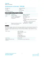
Bluetooth AT Data Module (external antenna) 

BTM421 

Bluetooth AT Data Module (with integrated antenna) 

DVK – BTM420  Development board with BTM420 module soldered in place 
DVK – BTM421  Development board with BTM421 module soldered in place 

G

ENERAL 

C

OMMENTS


All information in this document is subject to change. Please check with Laird Technologies for the latest 
information before commencing a design. If in doubt, ask. 

Refer to the schematic BTDMD-R-001.pdf for the Development Kit on the following two pages for examples 
of typical pin connections. A PDF of the schematic can be downloaded from the product web page. 

Содержание BTM420

Страница 1: ...BTM420 421 DATA MODULE USER MANUAL VERSION 3 0 Americas 1 800 492 2320 Europe 44 1628 858 940 Hong Kong 852 2923 0610 www lairdtech com wireless ...

Страница 2: ...bluetooth 2 Laird Americas 1 800 492 2320 Europe 44 1628 858 940 Hong Kong 852 2923 0610 REVISION HISTORY Revision Date Description Approved By 1 0 22 June 2010 Initial Release Jonathan Kaye 2 0 28 May 2012 Changes and Revisions Jonathan Kaye 3 0 04 Jan 2013 Formatting New Hardware Diagrams FCC Statement updates Jonathan Kaye ...

Страница 3: ...ifications 5 Pin Definitions 7 Operating Parameters 8 Voltage Specifications 9 FCC Regulatory Statements 10 BTM420 FCC and Industry Canada Statements 10 BTM421 FCC and Industry Canada Statements 11 EU Declaration of Conformity BTM420 12 EU Declaration of Conformity BTM421 13 Mechanical Drawings 14 BTM420 Mechanical Details 14 BTM420 Mechanical Details 15 BTM420 Mechanical Details 16 BTM421 Mechani...

Страница 4: ...choice for applications where designers need both performance and minimum size For maximum flexibility in systems integration the modules are designed to support separate power supplies for I O and the USB interface These modules present an HCI interface through a USB interface and are fully qualified as Bluetooth Controller Subsystem Products This allows designers to integrate them existing pre a...

Страница 5: ... pad BTM420 4 dBmi TBC from integrated antenna BTM421 Receive Sensitivity 84dBm Range 30m Data Transfer Rate Up to 2 1 Mbps Antenna Modes External Antenna 50 Ohm matched SMT pad BTM420 Integrated Antenna option 0 dB multiplayer ceramic TBC BTM421 USB Interface Compliance Version 1 1 Support Version 2 0 Supply Voltage 3 1 V to 3 3 V General Purpose Interface I O 2 general purpose I O pins for LEDs ...

Страница 6: ...2 wire and 3 wire hardware coexistence schemes supported Connections Interface Surface Mount Pads External Antenna Pad for 50 Ohm antenna BTM420 Physical Dimensions 12 5 mm x 18 0 mm x 3 4 mm BTM420 12 5 mm x 24 0 mm x 3 4 mm BTM421 Weight 3 grams Environmental Operating Temperature 30 C to 70 C Storage Temperature 40 C to 85 C Approvals Bluetooth Qualified as a Controller Subsystem Product FCC Li...

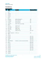
Страница 7: ...I bus serial I P VIO 11 SPI_CLK SPI bus clock I P VIO 12 VDD_USB USB UART supply voltage 15 GND 16 PCM_IN PCM clock I P VIO 17 PCM_SYNC PCM sync I P VIO 18 PCM_CLK PCM click I P VIO 19 PCM_OUT PCM Data O P VIO 20 RESET Module reset I P See note 2 21 Unused 22 GPIO2 UART_DCD I O for host VIO 23 GND 24 Unused 25 Unused See note 3 26 Unused See note 3 27 Unused See note 3 28 GND See note 3 29 ANT BTM...

Страница 8: ... D VUSB 48 Unused 49 Unused 50 Unused 1 Unused pins may have internal connections and must not be connected 2 Reset input is active low Input is pulled up to VDD_IN via 22k Minimum reset pulse width is 5 ms 3 Pins 25 37 should be left not connected on modules with integrated antennae BTM411 BTM421 and BTM431 Operating Parameters Table 4 Recommended Operating Conditions Recommended Operating Condit...

Страница 9: ...0 4 0 8 1 7 VDD_USB 1 9 0 4 0 4 Output Voltage Levels 1 7 VDD_USB_1 9 Voh lout 4mA VDD_USB 0 4 Vol lout 4mA Output Voltage Levels 2 7 VDD_USB 3 0 Voh lout 4mA VDD_USB 2 0 Vol lout 4mA 0 2 Note VDD_USB must be connected to power the USB and UART interfaces Table 6 Logic Levels VIO Logic Levels VIO INPUT VOLTAGE LEVELS MIN TYP MAX Vih 0 7VDD_IO Vil 2 7 VDD_IO 3 0 0 4 0 8 1 7 VDD_IO 1 9 0 4 0 4 Outpu...

Страница 10: ...nction with any other antenna or transmitter This module was approved with the following antenna RF Solutions ANT 24G WHJ SMA 0 dBi Operation of this module with any other antenna will require additional testing to be performed Co location with other radio transmitting devices operating concurrently in the same band will require additional testing and certification Designers should note the distin...

Страница 11: ...nna or transmitter Co location with other radio transmitting devices operating concurrently in the same band will require additional testing and certification Designers should note the distinction that the FCC makes regarding portable and mobile devices Mobile devices are defined as products that are not used closer than 20 cm to the human body whereas portable devices can be used closer than 20 c...

Страница 12: ...N 301 489 17 V2 1 1 Emissions EN55022 2006 A1 2000 A2 2006 ClassB Immunity EN61000 4 2 1995 A1 1998 A2 2001 EN61000 4 3 2002 A1 2002 3 2 Means of the efficient use of the radio frequency spectrum EN 300 328 V1 7 1 2006 10 Declaration We Laird Technologies declare under our sole responsibility that the essential radio test suites have been carried out and that the above product to which this declar...

Страница 13: ...N 301 489 17 V2 1 1 Emissions EN55022 2006 A1 2000 A2 2006 ClassB Immunity EN61000 4 2 1995 A1 1998 A2 2001 EN61000 4 3 2002 A1 2002 3 2 Means of the efficient use of the radio frequency spectrum EN 300 328 V1 7 1 2006 10 Declaration We Laird Technologies declare under our sole responsibility that the essential radio test suites have been carried out and that the above product to which this declar...

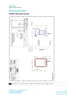
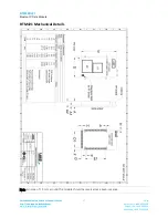
Страница 14: ...Center http ews support lairdtech com www lairdtech com bluetooth 14 Laird Americas 1 800 492 2320 Europe 44 1628 858 940 Hong Kong 852 2923 0610 MECHANICAL DRAWINGS BTM420 Mechanical Details Note An area of 1 5 mm around the module should be reserved as a keep out area ...

Страница 15: ...s Support Center http ews support lairdtech com www lairdtech com bluetooth 15 Laird Americas 1 800 492 2320 Europe 44 1628 858 940 Hong Kong 852 2923 0610 BTM420 Mechanical Details Note An area of 1 5 mm around the module should be reserved as a keep out area ...

Страница 16: ... bluetooth 16 Laird Americas 1 800 492 2320 Europe 44 1628 858 940 Hong Kong 852 2923 0610 BTM420 Mechanical Details WARNING Test point dimensions are for reference only DO NOT make electrical connections to these test points this will void the warranty Laird does not recommend routing on the top layer underneath the module ...

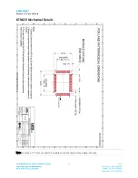
Страница 17: ...s Support Center http ews support lairdtech com www lairdtech com bluetooth 17 Laird Americas 1 800 492 2320 Europe 44 1628 858 940 Hong Kong 852 2923 0610 BTM421 Mechanical Details Note An area of 1 5 mm around the module should be reserved as a keep out area ...

Страница 18: ...s Support Center http ews support lairdtech com www lairdtech com bluetooth 18 Laird Americas 1 800 492 2320 Europe 44 1628 858 940 Hong Kong 852 2923 0610 BTM421 Mechanical Details Note An area of 1 5 mm around the module should be reserved as a keep out area ...

Страница 19: ...s Support Center http ews support lairdtech com www lairdtech com bluetooth 19 Laird Americas 1 800 492 2320 Europe 44 1628 858 940 Hong Kong 852 2923 0610 BTM421 Mechanical Details Note An area of 1 5 mm around the module should be reserved as a keep out area ...

Страница 20: ...40 Hong Kong 852 2923 0610 BTM421 Mechanical Details WARNING Test point dimensions are for reference only DO NOT make electrical connections to these test points this will void the warranty Laird does not recommend routing on the top layer underneath the module The Development Kit Schematics for this product can be accessed from the following link Development Kit Schematics BTM420 BTM421 ...

Страница 21: ...odule with integrated antenna DVK BTM420 Development board with BTM420 module soldered in place DVK BTM421 Development board with BTM421 module soldered in place GENERAL COMMENTS All information in this document is subject to change Please check with Laird Technologies for the latest information before commencing a design If in doubt ask Refer to the schematic BTDMD R 001 pdf for the Development K...

Страница 22: ...erves the right to make periodic modifications of this product without obligation to notify any person or entity of such revision Copying duplicating selling or otherwise distributing any part of this product or accompanying documentation software without the prior consent of an authorized representative of Laird Technologies Inc is strictly prohibited All brands and product names in this publicat...

Отзывы: