background image

47 


A

CCESSORY 

& S

UPPLY 

C

HECKLIST


I

TEM 

D

ESCRIPTION 

Q

TY

.


O

PTIONS


98-0130


CASTER SET: Heavy duty, roll & swivel lock. (Set of 4)


A

BRASIVES


Resin bond, non-adhesive abrasive cloth strips.


Pre-Marked, 60 grit and finer covers 25" drum 12 times


Pre-Marked, 36 grit covers 25" drum 9  times


Pre-Cut, grit includes 3 wraps for 25" drums


Pre-Cut


Pre-


Marked


Size and Description


25"


60-5024


24 GRIT: Surface rough sawn boards, stock & glue removal


60-5036


60-9036


36 GRIT: Surface rough sawn boards, stock & glue removal.


60-5060


60-9060


60 GRIT: Surfacing and dimensioning boards, trueing warped boards.


60-5080


60-9080


80 GRIT: Surfacing, light dimensioning, remove planer ripples.


60-5100


60-9100


100 GRIT: Light surfacing, remove planer ripples.


60-5120


60-9120


120 GRIT: Light surfacing, minimal stock removal.


60-5150


60-9150


150 GRIT: Finish sanding, minimal stock removal.


60-5180


60-9180


180 GRIT: Finish sanding, not for stock removal.


60-5220


60-9220


220 GRIT: Finish sanding, not for stock removal.


60-5000


n/a


Assortment: 1 strip each of 36, 80, 120 grit.


60-0505 

ABRASIVE CLEANING STICK


C

ONVEYOR 

B

ELTS


100 grit abrasive with reinforced backing.


6
0
-
0
3
3
7


          60-0324


36" Power Feed Bed with 2" diameter Drive Roller. 


Содержание SuperMax 25x2

Страница 1: ...OWNERS S MANUAL 25x2 SuperMax Drum Sander LagunaTools com...

Страница 2: ...Laguna Tools machine for your shop Regards Torben Helshoj President Founder Laguna Tools This manual applies to the 25x2 double head drum sanders Enter the model number serial number and purchase info...

Страница 3: ...Depth Gauge 17 Selecting Drum Abrasives 18 Tips For Maximum Performance 19 TROUBLESHOOTING Troubleshooting Guide Motors 21 Troubleshooting Guide Machine 22 Troubleshooting Guide Operations 24 SERVICIN...

Страница 4: ...REN AWAY All visitors should be kept safe distance from work area 6 MAKE WORKSHOP KID PROOF with padlocks master switches or by removing starter keys 7 DON T FORCE TOOL It will do the job better and s...

Страница 5: ...o persons 18 NEVER STAND ON TOOL Serious injury could occur if the tool is tipped or if the cutting tool is unintentionally contacted 19 CHECK DAMAGED PARTS Before further use of the too a guard or ot...

Страница 6: ...eo QR code Below is a QR code which links to a set up video for the 25 x 2 sander Scan the QR code with your smartphone to be directed to the video at LagunaTools com Tension Rollers Height Adjustment...

Страница 7: ...s one each for the right and left column tubes Important These set screws are tightened for shipping and must be loosened and readjusted before operating either the height adjustment mechanism or the...

Страница 8: ...ords are not recommended but if used should be of at least 10 gauge wire for lengths up to 10 and of at least 8 gauge wire for longer lengths Views of junction box under conveyor motor with cord insta...

Страница 9: ...ults follow the recommendations of the manufacturer of your dust collection equipment CHECKING DRUM ALIGNMENT The sander was shipped from the factory preadjusted with the drum s aligned to the con vey...

Страница 10: ...stment indicators to zero on both sides Toset loosen the hex nut then moving the indicator scale so that the zero mark is directly under the pointer and retightening the hex nut see Fig 7 Likewise zer...

Страница 11: ...ustment besuretoloosenbothoftheset screwslocatedon the front of bothtable support castings see Fig 3 and Fig 9 to allow the table support to slide on Fig 9 Table height adjustment both column tubes Th...

Страница 12: ...trailing edge of the wrap properly cut rewrap the drum and insert the tapered end through the slot in the right inboard end of the drum Insert the tapered end into the inboard take up fastener Pull u...

Страница 13: ...nstall Fig 10 d Insert tapered end into outboard slot Fig 10 e Wrap around drum without overlap Fig 10 f Mark wrap where it crosses drum edge Fig 10 g Insert tapered end into inboardslot Fig 10 h Allo...

Страница 14: ...to begin to use the sander The basic operating procedure for all drum sander models is asfollows 1 Set depth of cut 2 Start drum s 3 Start conveyor and select feedrate 4 Start dust collector system 5...

Страница 15: ...ither the primary or secondary drum can be used alone Front Drum To adjust the front drum set the drum height equal to the thickness of the piece to be processed Thisismosteasilydoneasfollows Lowerthe...

Страница 16: ...h of sanding Aslowerfeedrateprovidesmorerevolu tions of the drum per inch of sanding to allow a greater depth of cut and smoother sanding TheIntellisandcontrol SeeFig 13 continuously monitors the load...

Страница 17: ...til the drum s wrapped with abrasive touches the con veyortable Make sure the indicator is pointing at zero If not loosen the two screws at the bottom of the indicator and slide indicator until pointi...

Страница 18: ...e toburnish ing because of its open pores Selecting Grit Combinations The chart shown is a general guide to consult when selecting grits to use on dual drum machines and setting the rear drum This cha...

Страница 19: ...eces thicker than 3 4 should be longer than the minimum normally recommended to prevent tipping of the stock see Specifications Goingtolongerpieces is especiallyimportantwhensandingboxesor other tall...

Страница 20: ...o 1 hour then using a brush to remove any build up orburns Drytheabrasivestripscompletelybefore reuse In some cases build ups resulting from burns can beremoved with Plexiglas held on edge over a rota...

Страница 21: ...RS Problem PossibleCause Solution Motors do not start 1 Main power cord Plug in primary power unplugged from receptacle cord 2 Circuit fuse blown or circuit Replace fuse or reset breaker tripped break...

Страница 22: ...t collection 4 Inadequate abrasive 5 Stockfedat 90 angle to drum Reduce depth of cut Use slower feed rate Increaseairflow at dust ports Use open coat abrasive Anglestocktoavoidresin line build up Conv...

Страница 23: ...djust belt rollers misaligned 3 Conveyor table not flat Readjust by leveling with and square leg glides 4 Conveyor belt worn or Replace conveyor belt defective 5 Roller bushings elongated Replace bush...

Страница 24: ...ar motorstalling ExcessiveV belttension Set screw loose on shaft couplerbetweengearmotor and conveyor tighten Conveyor bushings dry lubricate Rippled sanded surface uniformly spaced ripples 1 Excessiv...

Страница 25: ...asive strips 4 Abrasive is too fine 5 Abrasivestrips overlapped 6 Drum out of alignment Increase feed rate Reduce depth of cut or increase grit coarseness Reduce depth of cut cleanstripsorreplace Repl...

Страница 26: ...ily further adjustments may be necessary as outlinedbelow Followingthesestepsshouldresult in smooth operation Readjustment Procedure 1 Loosen the set screws located at the front of the table support c...

Страница 27: ...smooth and even If not adjust the gears for good mesh Fig 18 Measure the space between the miter gear and the adjusting screw support that holds the height adjusting screw in place Fig 19 The distance...

Страница 28: ...r the feed table has been lev eled loosenallfourtensionrollersuspensionbolts Fig 22 Comparing drum support casting heights see Fig 26 Raise the tension roller suspension assembly to its highest positi...

Страница 29: ...um can barely be turned by hand Measure at both sides of the drum to check that the secondary drum is parallel to the table To adjust the secondary drum alignment use the right and left drum adjustmen...

Страница 30: ...width of the board approxi mately 2 1 4 from the end of the board If a snipe mark occurs on the trailing end of the board adjust the infeed tension roller Tensionroller pres surecanbeadjustedtwoways e...

Страница 31: ...r re installation Note If the conveyor belt continually tracks to one side of the machine first try reversing the belt on the conveyor bed If this doesn t remedy the problem place a level on the conve...

Страница 32: ...lt and replace it with the newV belt Machine Reassembly 1 Toreassemble the unit after replacing the V belt first place the transfer rod back through the machine Tighten the shaft collar Reinstall the...

Страница 33: ...place Lift control board from housing Install the new controller referring to the correct electrical diagram and reverse the disassembly procedure Toreplace the on off switch remove the two screwshold...

Страница 34: ...G 30 5206 2 13 SUPPORT ADJUSTING SCREW 30 1112 2 14 SUPPORT OUTBOARD TABLE 30 5204 1 15 HEX NUT 5 16 18 12 0003 4 16 FLAT WASHER 5 16 11 0206 4 17 BRASS TIPPED SET SCREW 5 16 18X3 4 10 9906 4 18 KNOB...

Страница 35: ...ASE COLUMN 30 1101 1 2 36 LEVELING FEET 20 0655 4 37 HEX NUT 3 8 16 12 005 8 38 BASE SUPPORT BRACKET 40 0230 1 39 RETAINING RING E12 20 0752 1 40 OUTBOARD HEIGHT ADJ SCREW 30 1211 1 41 BEARING R8ZZ BB...

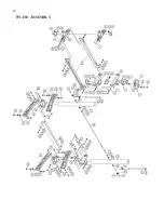
Страница 36: ...36 STAND ASSEMBLY...

Страница 37: ...8X1 10 1204 6 15 HEX CAP SCREW 5 16 18X1 1 4 10 9106 2 16 FLAT WASHER 5 16 11 0206 10 17 SPACER 5 16 I D 30 1305 2 18 BEARING 50 3067 4 19 OUTBOARD DRUM MOUNT BRACKET 40 0519 1 20 HEX NUT 5 16 18 12 0...

Страница 38: ...1028A 1 50 PHILLIPS FILLISTER HEAD SCREW 8 32X1 10 3107 6 51 COMPRESSION SPRING 20 3268 6 52 CARRIAGE BOLT 5 16 18X3 4 10 1203 4 53 FLAT WASHER 3 16 913002 253 2 54 TENSION ROLLER BASE BRACKET 40 030...

Страница 39: ...39 DUAL DRUM HEAD ASSEMBLY...

Страница 40: ...IDE RAIL RIGHT 40 4144 1 14 ROLLER SUPPORT BRACKET 635DS 338 1 15 DRIVEN ROLLER 30 3106 1 16 HEX CAP SCREW 3 8 16X3 4 480BS 177 4 17 FLANGE LOCK NUT 3 8 16 12 0209 16 18 CONVEYOR BED 40 4101 1 19 SIDE...

Страница 41: ...30 3102 1 45 CARRIAGE BOLT 5 16 18X1 10 1204 4 46 MOTOR 5HP 1Ph 70 0507 1 47 HEX NUT 10 32UNF 480BS 216 2 48 SPRING WASHER 5 16 480BS 167 4 49 LOWER INNER BELT GUARD 40 1000A 1 50 LOCK WASHER M6 635D...

Страница 42: ...S 350 3 66 STRAIN RELIEF PG 21 PG 21 1 67 JUNCTION BOX 913003 354 1 68 RUBBER BUSHING D25 PLAREVO1216 205 1 69 SCREW M4X0 7X6 913003 356 4 70 SCREW M6X1 0X8 913003 357 4 71 SCREW M5X0 8X8 913003 361 1...

Страница 43: ...43 CONVEYOR MOTOR...

Страница 44: ...r Direct driveDC motor Infinitelyvariablefrom0to15feetperminutewithIntellisand Conveyor Belt 100 grit abrasive conveyor belt included Drive Motor 5 HP TEFC 1 PH 1 740 RPM 208 230 volts 60 HZ Minimum S...

Страница 45: ...45 CS DE S CURIT...

Страница 46: ...de v tements amples de gants de bracelets de colliers et autres bijoux pouvant tre happ s par les parties mo biles de la machines Portez des chaussures antid ra pantes et rassemblez et couvrez les ch...

Страница 47: ...moval 60 5060 60 9060 60GRIT Surfacinganddimensioningboards trueingwarpedboards 60 5080 60 9080 80 GRIT Surfacing light dimensioning remove planer ripples 60 5100 60 9100 100 GRIT Light surfacing remo...

Страница 48: ...M AND BELT GUARDING IN PLACE KEEPHANDSANDCLOTHINGAWAYFROMOPERATINGDRUM S BELT AND PULLEYS ALWAYSMAINTAIN CONTROL OF STOCK TO AVOID KICKBACK KNOW HOW TO PREVENT IT ALWAYSDISCONNECT ELECTRICAL POWER BEF...

Отзывы: