laguna Revo 1836 Скачать руководство пользователя страница 5

 
Safety Rules. 


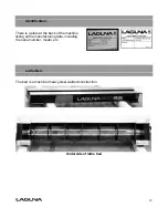
"WARNING":  For Your Own Safety Read Instruction Manual before Operating Lathe 


(a)


Wear eye protection. 

(b)


Do not wear gloves, a necktie, or loose clothing. 

(c)


Tighten all locks before operating. 

(d)


Rotate work piece by hand before applying power. 

(e)


Rough out work piece before installing on faceplate. 

(f)


Do not mount split work piece or one containing a knot. 

(g)


Use lowest speed when starting new work piece. 


1. 

KEEP GUARDS IN PLACE and in working order. 


2. 

REMOVE ADJUSTING KEYS AND WRENCHES. Form habit of checking to see that keys 
and adjusting wrenches are removed from tool before turning it on.  


3. 

KEEP WORK AREA CLEAN. Cluttered areas and benches invite accidents.  


4.

  DON'T USE IN A DANGEROUS ENVIRONMENT. Don't use power tools in damp or wet 

locations, or expose them to rain. Keep work area well lighted. 


5.

  KEEP CHILDREN AWAY. All visitors should be kept at a safe distance from  

the work area.  


6.

  MAKE YOUR WORKSHOP KID PROOF with padlocks, master switches,  


or by removing starter keys.  


7. 

DON'T FORCE TOOL. It will do the job better and safer at the rate for which it was 
designed. 


8.

  USE RIGHT TOOL. Don't force tool or attachment to do a job for which it was not 

designed.  


9. 

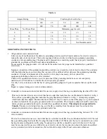
USE PROPER EXTENSION CORD. Make sure your extension cord is in good condition. 
When using an extension cord, be sure to use one heavy enough to carry the current your 
product will draw. An undersized cord will cause a drop in line voltage resulting in loss of 
power and overheating. Tabe A shows the correct size to use depending on cord length
and nameplate ampere rating. If in doubt, use the next heavier gauge. The smaller the 
gauge number, the heavier the chord. 


10.

 WEAR PROPER APPAREL Do not wear loose clothing, gloves, neckties, rings, bracelets, 

or other jewelry which may get caught in moving parts. Nonslip footwear is recommended. 
Wear protective hair covering to contain long hair. 


11. 

ALWAYS USE SAFETY GLASSES. Also use a face or dust mask if cutting operation is 
dusty. Everyday eyeglasses only have impact resistant lenses, they are NOT safety 
glasses. 


12. 

SECURE WORK. Use clamps or a vise to hold the work when practical.  
It's safer than using your hand and it frees both hands to operate the tool. 


13. 

DON'T OVERREACH. Keep proper footing and balance at all times. 


14.

 MAINTAIN TOOLS WITH CARE. Keep tools sharp and clean for best and safest 

performance. Follow instructions for lubricating and changing accessories.  

15. 

DISCONNECT TOOLS before servicing and when changing accessories, such as blades, 
bits, cutters, and the like.  


16.

  REDUCE THE RISK OF UNINTENTIONAL STARTING. Make sure power switch is in the 

OFF position before plugging the machine in.  


17.

 USE RECOMMENDED ACCESSORIES. Consult the owner's manual for recommended 

accessories. The use of improper accessories may cause risk of injury to persons. 


18.

 NEVER STAND ON TOOL Serious injury could occur if the tool is tipped or if the cutting 

tool is unintentionally contacted. 


19.

  CHECK DAMAGED PARTS. Before further use of the tool, a guard or other part that is 

damaged should be carefully checked to determine that it will operate properly and 
perform its intended function - check for alignment of moving parts, binding of moving 
parts, breakage of parts, mounting, and any other conditions that may affect its operation. 
A guard or other part that is damaged should be properly repaired or replaced. 


20. 

DIRECTION OF FEED. Feed work into a blade or cutter against the direction of rotation of 
the blade or cutter only. 


21. 

NEVER LEAVE TOOL RUNNING UNATTENDED. TURN POWER OFF.  Don't leave tool 
until it comes to a complete stop.   


Règles


de


sécurité


"AVERTISSEMENT" : Pour votre sécurité, lire le manuel d'instru on a en vement avant d' liser le tour à bois.


(a) 

Portez des lune es de protec


(b) 

Ne pas porter de gants, de cravate, ou de vêtements amples. 

(c) 

Serrer tous les verrous avant d'opérer la machine. 

(d) 

Tourner la pièce à la main avant d'appliquer le courant. 

(e) 

Débiter grossièrement la pièce avant de l'installer sur le plateau de montage. 

(f) 

Ne pas monter une pièce fendue ou comportant un nœud. 

(g) 

U liser la vitesse la plus lente au démarrage d'une nouvelle pièce. 


1. CONSERVEZ TOUS LES DISPOSITIFS DE PROTECTION EN PLACE et en bon état de fonc onnement. 

2. ENLEVEZ LES CLÉS ET OUTILS. Prenez l'habitude de véri

er si les clés et autres ou ls ne sont pas trop près de la 

machine avant de la démarrer. 

3. CONSERVEZ LA SURFACE DE TRAVAIL PROPRE ET LIBRE D'ENTRAVES. Les endroits encombrés augmentent le risque 

d'accident. 

4. NE PAS UTILISER DANS LES ENVIRONNEMENTS DANGEREUX. N' lisez pas d'ou ls électriques dans les endroits 

humides, détrempés, ou sous la pluie. Conservez l'espace de travail bien éclairé. 

5. TENEZ LES ENFANTS À L'ÉCART. Tous les visiteurs doivent être tenus à une distance sécuritaire de l'aire de travail. 

6. RENDEZ L'ATELIER À L'ÉPREUVE DES ENFANTS avec des verrous, des interrupteurs principaux ou en enlevant les clés 

de démarrage sur les 


7. NE FORCEZ PAS L'OUTIL. L'ou l e

ectuera un meilleur travail et de façon sécuritaire s'il est u lisé au rythme pour 

lequel il a été conçu. 

8. UTILISEZ L'OUTIL APPROPRIÉ. Ne forcez pas un ou l ou un accessoire pour e

ectuer un travail pour lequel il n'a pas 

été conçu. 

9. UTILISEZ UNE RALLONGE ÉLECTRIQUE APPROPRIÉE. Assurez-vous que votre rallonge électrique est en bon état et 

que le calibre du 

lage soit adéquat pour transporter le courant que la machine a besoin. Une rallonge de trop 

faible calibre induira une perte d'intensité du voltage, ce qui provoquera une surchau

e et une perte de puissance. 

Le tableau A indique le bon calibre à u liser en fonc on de la longueur de la rallonge et de la demande en intensité 

du moteur. En cas de doute, u lisez la rallonge de calibre plus fort. Plus le numéro est pe t, plus la rallonge est de 

fort calibre. 

10. PORTEZ DES VÊTEMENTS APPROPRIÉS. Ne portez pas de vêtements amples, des gants, des colliers, des bracelets, 

ou tout autre bijou ou accessoire qui pourrait être entraîné par des pièces mobiles. Des souliers à semelle 

an dérapante sont également recommandés.  achez les cheveux longs et portez un bonnet pour contenir la 

chevelure trop abondante. 

11. PORTEZ DES LUNETTES DE PROTECTION. Portez également un masque contre la poussière si le travail exécuté 

dégage de la poussière. Veuillez prendre note que les lune es de prescrip

 ordinaire ne résistent pas aux 

impacts et qu'elles ne sont pas homologuées à  re de lune es de sécurité. 

12. IMMOBILISEZ VOTRE TRAVAIL.  lisez des serres ou un étau pour immobiliser votre travail lorsque c'est possible. 

C'est plus sécuritaire que d'u liser votre main, et ça permet de libérer vos deux mains pour opérer 

confortablement. 

13. NE VOUS ÉTIREZ PAS AU-DESSUS DE LA MACHINE. Demeurez solidement en équilibre sur vos pieds en tout temps. 

14. ENTRETENEZ LES OUTILS AVEC SOIN. Gardez les 

ls de coupe tranchants et propres pour en  rer les meilleures 

performances. Suivez les ins

 du fabricant pour la lubri

ca on et l'entr en des accessoires. 

15. DÉBRANCHEZ LES OUTILS avant d'en e

ectuer l'entr en ou lors du changement d'accessoires tels que lames ou 

couteaux. 

16. RÉDUISEZ LES RISQUES DE DÉMARRAGE NON INTENTIONNEL. Assurez-vous que l'interrupteur est en posi on 

fermée avant le branchement d'un ou l. 

17. UTILISEZ LES ACCESSOIRES RECOMMANDÉS. Consultez le manuel d'instru

 pour connaître les accessoires 

recommandés. L'u lisa on d'accessoires inappropriés pose des risques de blessures aux  lisateurs. 

18. NE VOUS TENEZ JAMAIS DEBOUT SUR UNE MACHINE. Des blessures graves pourraient survenir si la machine 

bascule ou si les 

ls coupants sont touchés accidentellement. 

19. VÉRIFIEZ LES PIÈCES ENDOMMAGÉES. Avant de poursuivre l'u lisa on d'un 

l, tout disposi f de prot

 ou 

toute pièce endommagée devra être inspecté pour déterminer si elle peut fonc onner correctement et selon 

l'u lisa on qui en est prévue. Véri

ez l'alignement des pièces mobiles à savoir s'il y a blocage, un bris, ou toute 

autre co

on qui nuirait à son  lisa on. Une pièce ou un protecteur endommagé doit être réparé ou remplacé. 

20. SENS D'ALIMENTATION. Alimentez la pièce vers la lame ou le couteau dans le sens contraire de sa rota on 

seulement. 

21. NE LAISSEZ JAMAIS UN OUTIL FONCTIONNER DANS SURVEILLANCE – ÉTEIGNEZ L'OUTIL. Ne laissez pas l'ou l sans 

surveillance jusqu'à ce qu'il s'arrête complètement. 

Содержание Revo 1836

Страница 1: ...lagunatools com lagunacleanair com supermaxtools com Owner s Manual Revo 1836 MLAREVO1836...

Страница 2: ...manship of all parts and materials that make up the machine unless otherwise specified Any part determined by Laguna Tools to have a defect will be repaired or replaced and shipped without charge The...

Страница 3: ...es and CNC routers and Plasma machines Through my hands on experience I work hard to make our machines better I strive to give you machines that inspire you to create works of art machines that are a...

Страница 4: ...eet 10 Receiving your machine 11 Introduction to your machine 11 Parts of the machine 11 What you will receive with the machine 16 Where to locate your machine 17 Unpacking your machine 18 Assembly an...

Страница 5: ...ce fendue ou comportant un n ud g U liser la vitesse la plus lente au d marrage d une nouvelle pi ce 1 CONSERVEZ TOUS LES DISPOSITIFS DE PROTECTION EN PLACE et en bon tat de fonc onnement 2 ENLEVEZ L...

Страница 6: ...receptacles that accept the tool s plug Repair or replace damaged or worn cord immediately 2 Grounded cord connected tools intended for use on a supply circuit having a nominal rating less than 150 v...

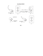
Страница 7: ...Fig 1...

Страница 8: ...e control panel We have supplied two concepts for locking the panel see below The cover can be made from wood or plastic First push down the emergency stop Then lock the cover together by putting padl...

Страница 9: ...8 Wooden safety cover Padlocks Emergency stop switch Plastic safety cover Padlocks...

Страница 10: ...hers Laguna Tools Inc is not responsible for additional tools or modifications sold or performed other than from by Laguna Tools Inc on any Laguna Tools Inc woodworking machine Warranty may be voided...

Страница 11: ...60hz single phase input 3 phase output Recommended breaker size 15 amp 15 amp Swing over bed 18 457mm 18 457mm Swing over banjo 13 5 343mm 13 5 343mm Outboard swing max 32 813mm 32 813mm Distance betw...

Страница 12: ...eavours to test machines prior to shipping to customers as movement can take place during transportation It must be noted that additional machine movement can take place between Laguna Tools and the e...

Страница 13: ...cation There is a plate at the back of the machine listing all the manufacturing data including the serial number model etc Lathe Bed The bed is a machined heavy steel welded construction Underside of...

Страница 14: ...t is very stable The legs are supplied with adjustable feet to allow the machine to be leveled Legs with adjustable feet assembled Head stock The head stock is cast iron and houses the variable speed...

Страница 15: ...to any position on the lathe bed and locked to suit the job at hand Tool rest The tool rest can be moved to any position on the lathe bed and locked to suit the job at hand The tool rest has a tall pr...

Страница 16: ...spindle A power cord with 220V plug is provided 110V The electrical control system VFD is housed at the back of the head stock The VFD converts single phase 110v to three phase There is a speed reado...

Страница 17: ...16 What you will receive with the lathe Head stock Tool rest Tail stock Drive live center storage Tool storage Leg Bed Banjo Adjustable feet Leg...

Страница 18: ...a few guidelines 1 There should be sufficient area at the front of the machine to allow you to work on it comfortably 2 There should be sufficient area at the back of the machine to allow access for a...

Страница 19: ...COULD CAUSE INJURY Lathe in packaging Leg Parts of the lathe Second leg Top packaging removed 2 Open the box and remove the parts sent with the lathe including the first leg Note The legs are heavy an...

Страница 20: ...the bed of the machine Note It is recommended that the head stock tool rest and tailstock be removed from the bed of the lathe to ease assembly Covered later in the manual Assembling the legs to the b...

Страница 21: ...ition and one to fit the fixing screws Note If you have any doubt about the described procedure seek professional assistance Do not attempt any procedure that you feel is unsafe or that you do not hav...

Страница 22: ...to the bed of the lathe and fit the stops Note If you have any doubt about the described procedure seek professional assistance Do not attempt any procedure that you feel is unsafe or that you do not...

Страница 23: ...that the washer recess fits into the slot in the bed Fit the banjo onto the bed with the bolt through the washer and assemble the nut onto the thread Adjust the nut so that the clamp handle locks the...

Страница 24: ...t is recommended that you use a 15 amp main breaker Note A qualified electrician must carry out the installation Cleaning the machine Remove the rust protection grease with WD 40 or a similar solvent...

Страница 25: ...far back as possible and this will eject the center Fitting the drive center into the head stock To remove the face plate from the head stock spindle insert the removal tool into the hole in the face...

Страница 26: ...ocedure described earlier Lathe controls Emergency stop button The emergency stop button will lock in the OFF position when fully depressed To reset it twist clockwise and it will pop out Forward reve...

Страница 27: ...llows the head stock to be released and moved to any position on the lathe bed It is located at the back of the head stock Emergency stop button Start stop buttons Speed display Forward reverse switch...

Страница 28: ...as follows 1 Disconnect the electric supply to the lathe 2 Open the pulley cover 3 Loosen the motor lock handle and lift the motor to the highest position with the motor adjustment handle then lock t...

Страница 29: ...obs Try the plunger in a few different holes to check that it inserts and removes smoothly The indexing plunger is spring loaded and this is used only to temporarily align the plunger in the selected...

Страница 30: ...29 Indexing holes Clamping knobs Hole selection indicator Hole selection Indexing plunger Indexing plunger engaged Indexing plunger disengaged...

Страница 31: ...none painted surfaces will rust if not protected It is recommended that they be protected by applying wax or a Teflon based lubricant to them Center point alignment and slide clearance adjustment The...

Страница 32: ...s above should be conducted on the head stock should it be required Note It is very unlikely that the headstock will require adjustment as it is not moved as often as the tailstock so has less tendenc...

Страница 33: ...points aligned Note It is recommended that the head stock be adjusted and not the tail stock If the tail stock is not adjusted parallel to the bed slide the center point will not be in alignment when...

Страница 34: ...urn the spindle by hand If the spindle will not turn check the reason for jamming 2 Capacitor faulty Replace the capacitor 3 Motor faulty Replace the motor 4 Power line overloaded Correct overloaded c...

Страница 35: ...floor Re level the machine ensuring that it has no movement 2 Damaged drive belt Replace the belt 3 Job is not balanced Change to slower speed and or balance the job 4 Damaged pulley Replace the pull...

Страница 36: ...35 Electrical drawing...

Страница 37: ...36 Exploded view drawings and parts list...

Страница 38: ...37...

Страница 39: ...O1836 114 Clamp Bolt 3 15 PLAREVO1836 115 Sleeve 2 16 PLAREVO1836 116 Rubber Sleeve 2 17 PLAREVO1836 117 Knob 1 18 PLAREVO1836 118 Headstock Adjusting Plate 1 19 PLAREVO1836 119 Clamp 2 20 PLAREVO1836...

Страница 40: ...1 51 PLAREVO1836 151 Knockout Rod 1 52 PLAREVO1836 152 Braking Resistor Cord 1 53 PLAREVO1836 153 Lock Handle 1 54 PLAREVO1836 154 Control Box 1 55 PLAREVO1836 155 Control Cord 1 56 PLAREVO1836 156 T...

Страница 41: ...EVO1836 186 Key 8x7x25 1 87 PLAREVO1836 187 Key 8x7x60 1 88 PLAREVO1836 188 E Ring E19 2 89 PLAREVO1836 189 E Ring E15 4 90 PLAREVO1836 190 E Ring E5 1 91 PLAREVO1836 191 C Ring R22 1 92 PLAREVO1836 1...

Страница 42: ...LAREVO1836 1121 Socket Head Button Screw M8x45 1 122 PLAREVO1836 1122 Socket Head Cap Screw 5 16 18UNCx1 2 3 123 PLAREVO1836 1123 Poly V Belt PJ8 190 1 124 PLAREVO1836 1124 Set Screw 3 16 24UNCx3 16 2...

Страница 43: ...3 8 8 147 PLAREVO1836 1147 Headstock Bracket 1 148 PLAREVO1836 1148 Socket Head Cap Screw 3 8 16UNCx1 1 4 2 149 PLAREVO1836 1149 Tailstock Bracket 1 150 PLAREVO1836 1150 Socket Head Cap Screw 3 8 16UN...

Страница 44: ...nal Headstock Guard Index Part Number Item Description Specification Qty 1 PLAREVO1836 201 Plunger 1 2 PLAREVO1836 202 Retaining Collar 2 3 PLAREVO1836 203 Guard 1 4 PLAREVO1836 204 Set Screw 1 4 20UN...

Страница 45: ...44...

Страница 46: ...REVO1836 119 Clamp 1 8 PLAREVO1836 114 Clamp Bolt 1 9 PLAREVO1836 115 Sleeve 1 10 PLAREVO1836 116 Rubber Sleeve 1 11 PLAREVO1836 1145 Cap 1 12 MPAREVO1836 189 E Ring E15 4 13 PLAREVO1836 185 Key 6x6x3...

Страница 47: ...2 PLAREVO1836 402 Draw Latch Assembly 1 3 PLAREVO1836 403 Hinge 1 4 PLAREVO1836 404 Pin 2 5 PLAREVO1836 147 Stop Bolt 1 6 PLAREVO1836 406 Socket Head Cap Screw M6x12 4 7 PLAREVO1836 407 Phillips Flat...

Страница 48: ...47 Optional Comparator Index Part Number Item Description Specification Qty 1 PLAREVO1836 501 Center 2 2 PLAREVO1836 502 Lock Handle 2...

Страница 49: ...48 Optional Industrial Flood Light Index Part Number Item Description Specification Qty 1 PLAREVO1836 601 Work Light 1 2 PLAREVO1836 602 Screw M4x15 4...

Страница 50: ...49...

Страница 51: ...813 Quick Release Fitting 1 14 PLAREVO1836 814 Pressure Vacuum Gauge 1 15 PLAREVO1836 815 Gauge Fitting 1 16 PLAREVO1836 816 Vacuum Switch 1 17 PLAREVO1836 817 H Type Fitting 1 18 PLAREVO1836 818 Flat...

Страница 52: ......

Страница 53: ...36 909 Spacer 4 10 PLAREVO1836 910 Cylinder 2 11 PLAREVO1836 911 Nylon Insert Lock Nut M10x1 5 4 12 PLAREVO1836 912 Support Bracket 2 13 PLAREVO1836 913 Bushing 2 14 PLAREVO1836 914 Socket Head Cap Sc...

Страница 54: ...Riser Blocks 2 2 PLAREVO1836 702 Socket Head Cap Screw 3 8 16UNCx3 1 2 4 3 PLAREVO1836 1115 Lock Washer 3 8 8 4 PLAREVO1836 1146 Socket Head Button Screw 1 4 20UNCx3 8 4 5 PLAREVO1836 705 Support Bra...

Страница 55: ...7 5 13 14 15 16 17 18 19 20 21 22 23 24 14 334 3 360 36 130 140 150 160 170 180 190 200 210 220 230 240 48 97 5 105 112 5 120 127 5 135 142 5 150 157 5 165 172 5 180 25 26 27 28 29 30 31 32 33 34 35 3...

Страница 56: ...1 949 474 1200 or email customerservice lagunatools com Laguna Tools is not responsible for errors or omissions Speci cations subject to change Machines may be shown with optional accessories 2018 Lag...

Отзывы: