background image

15

JX|6 & JX|8 Quadtec:I Jointers \ Setup   

Setup

Setup Overview (MUST READ)

When setting up your Jointer, please take a moment to read this overview prior to starting.

The machine comes mostly assembled. You will have to assemble the leveling feet and calibrate the
thickness scale.

After Setup, There may be a few adjustment to be made. All of these adjustments are done prior to shipping
the machine, however if additional adjustments are required please follow the adjustment guides.

 If you have any doubt about the described procedure, seek professional assistance. Do not

attempt any procedure that you feel is unsafe, or that you do not have the physical capability of achieving.

Placement & Unboxing

Your Machine will likely be delivered by a third party delivery service. Before unpacking your new machine,
first inspect the packaging, the invoice, and the shipping documents supplied by the driver. When unpacking
your machine, separate all enclosed items from the packing materials and inspect them for damages.
Ensure that there is no visible damage to either the packaging or the machine BEFORE the driver leaves.
Save all packaging materials until you are satisfied with the machine and/or have resolved any issues
concerning any missing or damaged items.

NOTICE!

·

ALL SHIPPING DAMAGE MUST BE NOTED UPON DELIVERY AND SIGNED BY THE OWNER AND THE DELIVERY DRIVER.

IF YOU FIND ANY DAMAGED ITEMS IN YOUR PACKAGE, YOU MUST CONTACT LAGUNA TOOLS TO FILE A COMPLAINT.

IN ORDER TO RETURN DAMAGED GOODS UNDER THE LIMITED WARRANTY TO LAGUNA TOOLS, INC., YOU MUST HAVE

THE ORIGINAL PACKAGING. ALL CLAIMS OF LOSS OR DAMAGED GOODS MUST BE REPORTED TO LAGUNA TOOLS

WITHIN 24 HOURS OF DELIVERY. PLEASE CONTACT THE LAGUNA TOOLS, INC. CUSTOMER SERVICE DEPARTMENT TO

MAKE CLAIMS FOR ANY DAMAGED ITEMS/PARTS. 

·

IT IS PROBABLE THAT YOU WILL FIND SAWDUST WITHIN YOUR MACHINE. THIS IS BECAUSE THE MACHINE HAS

BEEN TESTED PRIOR TO SHIPMENT FROM THE FACTORY AND OR LAGUNA TOOLS. WE TEST MACHINES PRIOR TO
SHIPPING TO CUSTOMERS, BUT MOVEMENT CAN TAKE PLACE DURING TRANSPORTATION. SOME ADJUSTMENTS

MAY HAVE TO BE UNDERTAKEN BY THE CUSTOMER. THESE ADJUSTMENTS ARE COVERED IN THE VARIOUS

SECTIONS OF THIS MANUAL.

Placement

Before you remove your machine from the packaging, select the area where you will use your machine.
There are no hard and fast rules for its location, but below are a few guidelines:

1. There should be sufficient area at the front of the machine to allow you to work on it comfortably.

2. There should be sufficient area at the back of the machine to allow access for adjustments and

maintenance to be conducted.

3. Adequate lighting. The better the lighting the more accurately and safely you will be able to work.

4. Solid floor. You should select a solid flat floor, preferably one made of concrete or something similar.

5. Locate it close to a power source and dust collection.

Содержание 506601

Страница 1: ...JX 6 JX 8 Quadtec I Jointers Owner s Manual 506601 MJ8X72P 0130 3 11 2021 ...

Страница 2: ...na 825 Bistline Dr Ste 101 West Columbia SC 29172 U S A Phone 1 800 234 1976 Minnesota 5250 West 74th St Edina MN 55439 U S A Phone 1 949 474 1200 lagunatools com supermaxtools com lagunacleanair com lagunalathe com LAGUNA EUROPE Walker Rd Bardon Hill Coalville LE67 1TU United Kingdom Phone 44 1530 516921 lagunatools uk DAKE CORPORATION 724 Robbins Road Grand Haven MI 49417 United States 1 800 937...

Страница 3: ...fety 4 Electrical Safety 8 Specifications 13 Machine Overview 14 Setup 15 Placement Unboxing 15 Inventory List 17 Assembling 18 Operation 21 Maintenance 24 Troubleshooting 27 Wiring 28 JX6 Quadtec I Parts 31 JX8 Quadtec I Parts 39 Warranty 47 ...

Страница 4: ...s to protecting your safety and preventing problems Safety Call outs DANGER A POTENTIALLY HAZARDOUS SITUATION WHICH IF NOT AVOIDED COULD RESULT IN DEATH OR SERIOUS INJURY SOMETIMES DISPLAYED AS WARNING A POTENTIALLY HAZARDOUS SITUATION WHICH IF NOT AVOIDED COULD RESULT IN DEATH OR SERIOUS INJURY SOMETIMES DISPLAYED AS CAUTION A POTENTIALLY HAZARDOUS SITUATION WHICH IF NOT AVOIDED MAY RESULT IN MIN...

Страница 5: ...ions are overlooked or ignored personal injury to the operator may result Safety equipment such as guards push sticks hold downs feather boards goggles dust masks and hearing protection can reduce your potential for injury But even the best guard won t make up for poor judgment carelessness or inattention Always use common sense and exercise caution in the workshop If a procedure feels dangerous d...

Страница 6: ...ng tool is unintentionally contacted STABLE MACHINE Unexpected movement during operation greatly increases risk of injury or loss of control Before starting verify machine is stable and mobile base if used is locked USE RECOMMENDED ACCESSORIES Consult this owner s manual or the manufacturer for recommended accessories Using improper accessories will increase the risk of serious injury UNATTENDED O...

Страница 7: ...AR BETTER TO TAKE SEVERAL SMALL CUTS RATHER THAN LARGE CUTS 6 DIRECTION OF CUT JOINTING AGAINST THE GRAIN OR JOINTING END GRAIN IS DANGEROUS AND COULD PRODUCE CHATTER OR EXCESSIVE CHIP OUT ALWAYS JOINT WITH THE GRAIN 7 GUARDS GUARDS ARE DESIGNED TO REDUCE THE RISK OF INJURY ALWAYS USE THE GUARDS IF IT IS IMPERATIVE TO USE THE MACHINE WITHOUT THE GUARDS RABBETING ALWAYS REPLACE THE GUARDS 8 CUTTING...

Страница 8: ...nter Kit part 510220 See 220 Volt Conversion for kit instructions Power Supply A separate electrical circuit should be used for each machine This circuit should not be less than the wiring listed below and should be protected with an appropriate circuit breaker based on the total running and start up amperage s listed below If an extension cord is used use only 3 wire extension cords which have 3 ...

Страница 9: ...PLUG RECEPTACLE Not Included WIRING Gauge See Jacket Printing CIRCUIT BREAKER 20Amp If this information is different than what is stated on the Motor Specification Plate omit this information It is possible that the documentation is outdated to a machine change such as a different motor Always check the motor plate prior to any wiring If any doubts please consult a certified electrician Know when ...

Страница 10: ...of least resistance for electric current to reduce the risk of electric shock This tool is equipped with an electric cord having an equipment grounding conductor and a grounding plug The plug must be plugged into a matching outlet that is properly installed and grounded in accordance with all local codes and ordinances Do not modify the plug provided if it will not fit the outlet have the proper o...

Страница 11: ...B if a properly grounded outlet is not available The temporary adapter should be used only until a properly grounded outlet can be installed by a qualified electrician This adapter is not permitted in Canada The green colored rigid ear lug and the like extending from the adapter must be connected to a permanent ground such as a properly grounded outlet box 3 Grounded cord connected tools intended ...

Страница 12: ...6 0 6 0 6 0 6 120 120 120 120 up to 25 25 50 50 100 100 150 18 AWG 16 AWG 16 AWG 14 AWG 6 10 6 10 6 10 6 10 120 120 120 120 up to 25 25 50 50 100 100 150 18 AWG 16 AWG 14 AWG 12 AWG 10 12 10 12 10 12 10 12 120 120 120 120 up to 25 25 50 50 100 100 150 16 AWG 16 AWG 14 AWG 12 AWG 12 16 12 16 12 16 120 120 120 up to 25 25 50 14 AWG 12 AWG GREATER THAN 50 FEET NOT RECOMMENDED MINIMUM GAUGE EXTENSION ...

Страница 13: ...TILT 45 90 DEGREE 45 90 DEGREE MAX DEPTH OF CUT 1 8 1 8 TABLE HEIGHT FROM FLOOR 31 31 SAFETY BAR SHUT OFF YES YES WHEELS BUILT IN YES YES BRACKET TO MOUNT LIGHT NO NO 110V OUTLET FOR LIGHT NO NO BRACKET TO MOUNT FEEDER NO NO DUST PORT DIAMETER 4 4 CUTTERHEAD INSERT 12 X 4 SIDED CARBIDE 4 ROW 20 X 4 SIDED CARBIDE 4 ROW CUTTERHEAD RPM 5500 5500 CUTTERHEAD DIAMETER 2 1 2 3 1 8 BED ADJUSTMENT PARALLEL...

Страница 14: ...s A Emergency Stop E STOP stops all functions of machine however power continues to machine NOTICE To reset E STOP rotate switch clockwise until the button pops out NOTICE E STOP bump bar red located on front of frame B ON OFF Switch Starts and Stops rotation of cutterhead NOTICE Will not work of the E STOP is engaged ...

Страница 15: ...HE OWNER AND THE DELIVERY DRIVER IF YOU FIND ANY DAMAGED ITEMS IN YOUR PACKAGE YOU MUST CONTACT LAGUNA TOOLS TO FILE A COMPLAINT IN ORDER TO RETURN DAMAGED GOODS UNDER THE LIMITED WARRANTY TO LAGUNA TOOLS INC YOU MUST HAVE THE ORIGINAL PACKAGING ALL CLAIMS OF LOSS OR DAMAGED GOODS MUST BE REPORTED TO LAGUNA TOOLS WITHIN 24 HOURS OF DELIVERY PLEASE CONTACT THE LAGUNA TOOLS INC CUSTOMER SERVICE DEPA...

Страница 16: ...n floor NOTICE Another option to remove the jointer from the pallet is to attach the included hooks to frame of machine at each of the four corners Fig 3 The hooks and bolts are included in the hardware kit The machine can then be lifted with a harness and forklift Remove and save hooks for later movement scenarios FIGURE 3 COVER REMOVED FROM CRATE FIGURE 4 CRATE REMOVED The Jointer comes packed i...

Страница 17: ...c bags before laying them out to inventory them Inventory 2 Push Blocks 1 3mm Hex Wrench 1 6mm Hex Wrench 1 8 10mm Wrench 1 11 13mm Wrench Tools items Required Assembly Adjustment T 25 Torx Wrench 3mm Hex Wrench 6mm Hex Wrench 8mm Hex Wrench not included 8 10mm Wrench 11 13mm Wrench DANGER FOR YOUR OWN SAFETY DO NOT CONNECT THE MACHINE TO THE POWER SOURCE UNTIL THE MACHINE IS COMPLETELY ASSEMBLED ...

Страница 18: ...e must be grounded and rated for the amperage given below Never replace a circuit breaker on an existing circuit with one of higher amperage without consulting a qualified electrician to ensure compliance with wiring codes If you are unsure about the wiring codes in your area or you plan to connect your machine to a shared circuit consult a qualified electrician Circuit Size 1 5 HP 110V Single Pha...

Страница 19: ... CONFORM TO THE NATIONAL ELECTRIC CODE AND ALL LOCAL CODES AND ORDINANCES Connecting Power See also wiring diagram page 33 1 Plug power cord into 20 Amp min 110 Volt Single Phase dedicated circuit WARNING DISCONNECT POWER SUPPLY TO JOINTER BEFORE CONTINUING ONLY CONNECT POWER WHEN REQUIRED ...

Страница 20: ...fence can be adjusted to use all or a portion of the cutterhead To adjust loosen the Locking Handle Fig 15 and turn the Adjustment Knob to position fence in desired location FIGURE 15 FENCE SLIDE COMPONENTS NOTICE The 90 degree position has an included reference STOP Fig 16 To adjust flip the stop into position loosen the lock nut and rotate the adjusting screw until the fence is at 90 degrees to ...

Страница 21: ...into cutterhead while maintaining contact of the stock on the bed and against the fence Maintain control and support of stock as the stock opens the guard and contacts the cutterhead Maintain a good firm stance while pushing stock across the jointer Move hands along stock when feeding to maintain control of stock Lift hands from stock as they come near cutterhead and reposition them on outfeed sid...

Страница 22: ...re is less chance of stock slippage when the fence is angled down toward the tables Fig 19 Angling the fence toward the tables is also a safer method to bevel when the application allows FIGURE 19 BEVELING NOTICE THE TWO 45 DEGREE POSITIONS INCLUDE TWO REFERENCE STOPS FIG 16 TO ADJUST LOOSEN THE LOCK NUT AND ROTATE THE ADJUSTING SCREW UNTIL THE FENCE IS AT 45 DEGREES TO THE TABLE ANGLED IN OR OUT ...

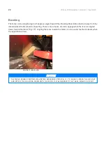
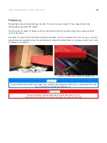
Страница 23: ...the Infeed Table Adjustment Handle Do not set deeper than 1 64 per pass Several passes may be required to reach the desired depth Adjust the infeed table for each pass 1 64 max until the rabbet is completed FIGURE 20 RABBETING FIGURE 21 REMOVING GUARD FOR RABBETING NOTICE SPRING LOADED GUARD RED MAY NEED TO BE REMOVED FOR RABBETING WIDE STOCK LOOSEN HEX BOLT AND LIFT GUARD WITH PIN FROM MACHINE FI...

Страница 24: ... knife inserts 2 Check knife inserts for nicks and sharpness 3 Generally inspect the machine for damage and loose or worn parts 4 Check the dust extraction for blockages and any large pieces that could cause blockages Monthly checks 1 Check the drive belt for wear splits and cuts 2 Clean the motor compartment and the motor to ensure that the motor cooling fins work efficiently 3 Generally inspect ...

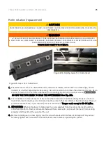
Страница 25: ...ove the knife insert screw Use a second Torx wrench to hold the cutterhead from rotating in position in another screw DO NOT USE YOUR HAND TO HOLD THE CUTTERHEAD See Fig 23b 2 It is advisable to rotate all inserts at the same time to maintain consistent cutting However if one or more knife inserts develops a nick rotate only those inserts that are affected Each knife insert has an etched reference...

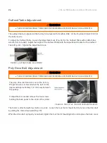
Страница 26: ...stment Lock FIGURE 24 OUTFEED TABLE ADJUSTMENT Poly Drive Belt Adjustment WARNING TURN OFF AND DISCONNECT POWER BEFORE PERFORMING ANY MAINTENANCE OR ADJUSTMENTS The poly drive belt tension is set at the factory Proper tension is achieved when the belt can be depressed approximately 1 4 mid way between the pulleys If adjustment is needed remove the four screws holding the back panel to the stand of...

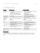
Страница 27: ...REMOVED IN ONE PASS 2 DULL KNIVES 1 REDUCE THE AMOUNT OF MATERIAL BEING REMOVED 2 ROTATE OR REPLACE KNIVES SNIPE 1 MATERIAL NOT SUPPORTED PROPERLY AS IT EXITS OUTFEED TABLE 2 OPERATOR PUSHING DOWN ON TRAILING END OF MATERIAL 3 OUTFEED TABLE TOO LOW 1 SUPPORT MATERIAL FOR ENTIRE CUT 2 ELIMINATE DOWNWARD PRESSURE ON TRAILING END 3 ADJUST OUTFEED TABLE LEVEL WITH CUTTERHEAD ACHIEVED FUZZY GRAIN 1 WOO...

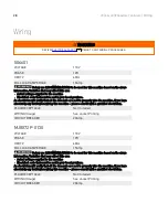
Страница 28: ...hen wiring this machine please consult with a qualified electrician PLUG RECEPTACLE Not Included WIRING Gauge See Jacket Printing CIRCUIT BREAKER 20Amp MJ8X72P 0130 VOLTAGE 110V PHASE 1PH HERTZ 60Hz FULL LOAD AMPERAGE 15Amp Below are RECOMMENDATIONS to be used for this machine based on the above information Variables that may affect this are Actual voltage supplied to the machine Electrical code t...

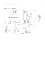
Страница 29: ...29 JX 6 JX 8 Quadtec I Jointers Wiring JX 6 Quadtec I 506601 ...

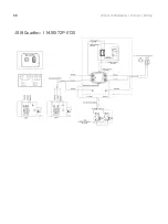
Страница 30: ...30 JX 6 JX 8 Quadtec I Jointers Wiring JX 8 Quadtec I MJ8X72P 0130 ...

Страница 31: ...31 JX 6 JX 8 Quadtec I Jointers JX6 Quadtec I Parts JX6 Quadtec I Parts Cutterhead Drivetrain ...

Страница 32: ...32 JX 6 JX 8 Quadtec I Jointers JX6 Quadtec I Parts Fence ...

Страница 33: ... BRACKET UPPER 1 5 130055 903 SLEEVE 1 6 130009 903 FIXING BLOCK 1 7 006003 097 FLAT WASHER 13 5 40X3 0 2 8 290003 901 BOLT 1 9 170047 901 STOP PLATE 1 10 011002 103 SPRING PIN 4X12 2 11 360068 901 FIXING ROD 1 12 009008 300 HEX NUT 7 16 14 17 4BX9 52H 1 13 170598 901 FENCE STOP 1 14 130007 903 PIVOT 1 15 290004 901 BOLT 1 16 009010 100 HEX NUT 1 2 20 19 05BX6 35H 2 17 360676 901 STUD PIVOT 2 18 0...

Страница 34: ...25133 001 SEGMENTED CUTTERHEAD QUADTEC1 1 35 925134 001 SEGMENTED CUTTERHEAD 4 SLOTS 1 925135 001 KNIFE INSERT 10PCS BOX 1 038201 101 TORX SCREW 10 32X1 2 040710 000 TORX WRENCH T 25 1 36 012003 009 KEY 5X5X25 1 37 030207 002 BALL BEARING 6203 1 38 050019 901 BEARING HOUSING 1 39 381427 902 PULLEY 6SLOT 1 40 001902 101 SET LOCK SCREW M6 1 0X10 1 41 174794 196 REAR BASE COVER L 1 42 200024 615 PACK...

Страница 35: ... 1 74 008006 100 HEX NUT M8 1 25 13BX6 5H 3 75 000102 104 CAP SCREW M5 0 8X12 2 76 130350 903 BUSHING 8 77 001901 102 SET LOCK SCREW M5 0 8X8 8 78 130351 903 CONNECTING ROD PLATE 2 79 001902 102 SET LOCK SCREW M6 1 0X8 10 80 361241 902 BUSHING 8 81 361374 902 ROD 4 82 130352 903 ROD PLATE 6 83 002603 101 CAP LOCK SCREW M5 0 8X10 16 84 174790 000 FIXING ROD PLATE 4 85 174784 904 FIXING PLATE 1 86 0...

Страница 36: ... 114 000801 101 ROUND HEAD HEX SCREW M6 1 0X10 6 115 006306 100 LOCK WASHER 9 8 17 8 2 116 003111 302 CAP SCREW 3 8 24X2 1 2 2 117 174783 904 LOCKING PLATE R 1 118 924851 001 CHIP HOOD ASSEMBLY 6 1 119 006002 032 FLAT WASHER 6 6 13X1 0 4 120 000304 203 PAN HEAD SCREW M6 1 0X12 4 122 901269 000 MOTOR ASSEMBLY 1 5HP 115V 230V 60HZ 1P H PREWIRED 115V 1 123 250036 615 DUST CHUTE 1 124 174933 196 STAND...

Страница 37: ...21 472001 056 CONNECT CORD SJT 18AWG 2C 2000MM 1 133 003801 107 CARRIAGE BOLT 5 16 18X3 4 4 134 006001 053 FLAT WASHER 8 5 19X2 0 4 135 014367 000 POLY V BELT 320J 6 1 136 250035 629 PUSH BLOCK 2 139 925093 001 EXTENSION ROLLER ASSEMBLY 6 1 140 010208 000 RETAINING RING ETW 12 2 141 361435 902 EXTENSION ROD 2 142 000103 103 CAP SCREW M6 1 0X12 8 143 130405 903 BUSHING BLOCK 4 144 250705 000 WING S...

Страница 38: ...REW 3 8 16X2 1 2 4 164 004001 101 KNOB 2 171 040003 000 HEX WRENCH 3MM 1 172 040006 000 HEX WRENCH 6MM 1 173 040201 000 OPEN WRENCH 8 10 1 174 040203 000 OPEN WRENCH 11 13 1 191 174932 000 LIMIT SWITCH BRACKET 2 192 002401 101 ROUND HEAD PHILLIPS LOCK SCREW W WASHER M4 0 7X12 4 10X0 8 4 193 040203 000 OPEN WRENCH 11 13MM 1 ...

Страница 39: ...39 JX 6 JX 8 Quadtec I Jointers JX8 Quadtec I Parts JX8 Quadtec I Parts Cutterhead Drivetrain ...

Страница 40: ...40 JX 6 JX 8 Quadtec I Jointers JX8 Quadtec I Parts Fence ...

Страница 41: ... LEAD SCREW 1 5 006001 087 FLAT WASHER 12 25X1 5 1 6 250372 615 FENCE TILT KNOB 2 7 360038 901 HANDLE ROD 2 8 003103 102 CAP SCREW 1 4 20X1 2 1 9 172285 905 FLAT WASHER 13 35X5 0 1 10 009104 200 LOCK NUT 1 2 12 19BX15H 1 11 011002 106 SPRING PIN 4X25 1 12 360074 901 CRANKSHAFT 1 13 360075 901 CLAMPING SCREW 1 14 130019 903 STOP PLATE 1 15 006001 091 FLAT WASHER 13 28X3 0 1 16 230035 000 UNIVERSAL ...

Страница 42: ...EX NUT 3 8 16 13 83BX6 68H 4 37 130008 903 CONNECT BLOCK 1 38 051334 196 FIXING ROD 1 39 130383 903 SQUARE NUT 1 2 12 1 40 006001 049 FLAT WASHER 8 5 16X2 0 8 41 006305 100 LOCK WASHER 8 2 13 7 12 42 000104 108 CAP SCREW M8 1 25X25 4 43 011002 105 SPRING PIN 4X20 1 44 380082 902 KEY 1 45 000701 103 FLAT HEAD HEX SCREW M5 0 8X12 3 46 171841 902 LEAD SCREW 1 41 006305 100 LOCK WASHER 8 2 13 7 4 47 0...

Страница 43: ...BUSHING 8 76 130352 903 ROD PLATE 6 77 174604 000 FIXING ROD PLATE 4 78 002603 101 CAP LOCK SCREW M5 0 8X10 16 79 361326 902 ROD 4 80 174784 904 FIXING PLATE 1 81 000103 108 CAP SCREW M6 1 0X25 2 82 006303 100 LOCK WASHER 6 5 10 5 7 83 130393 903 INCLINED BLOCK 1 84 361370 902 HANDLE SHAFT BOLT 1 85 002602 101 CAP LOCK SCREW M6 1 0X12 1 86 361327 902 HANDLE SHAFT BOLT 1 87 290028 901 SHOULDER SCRE...

Страница 44: ... 5X20 2 119 000304 203 PAN HEAD SCREW M6 1 0X12 8 120 006002 032 FLAT WASHER 6 6 13X1 0 8 121 250052 615 DUST CHUTE 1 122 174937 196 STAND 1 123 250399 615 WHEEL 4 124 008306 100 LOCK NUT M8 1 25 13BX9H 4 125 000003 313 HEX SCREW M8 1 25X60 4 126 230388 000 TRIANGLE KNOB 2 127 001603 102 ROUND HEAD PHILLIPS SCREW W WASHER M6 1 0X10 6 13 2X1 0 4 128 174595 196 PULLEY COVER 1 129 170445 196 COVER 1 ...

Страница 45: ...4 135 006001 053 FLAT WASHER 8 5 19X2 0 4 136 014361 000 POLY V BELT 300J 7 1 137 901336 001 MOTOR ASSEMBLY 1 75HP 115V 230V 60HZ 1 PH PREWIRED 115V 1 1 960044 001 MOTOR ASSEMBLY 1 75HP 115V 230V 60HZ 1 PH 1 2 381410 902 MOTOR PULLEY 7 SLOTS 1 3 001902 102 SET LOCK SCREW M6 1 0X8 1 138 006307 100 LOCK WASHER 10 2 18 5 1 139 006001 069 FLAT WASHER 10 20X3 0 1 150 000104 106 CAP SCREW M8 1 25X20 2 1...

Страница 46: ...NCY STOP PLATE 1 174 340007 615 BLOCK 5 175 020005 000 STRAIN RELIEF SB8R 3 1 176 020008 000 STRAIN RELIEF SBR5 2 1 177 471037 103 CONNECT CORD 18AWG 1C 700MM 1 179 002401 101 ROUND HEAD PHILLIPS LOCK SCREW W WASHER M4 0 7X12 4 10X0 8 4 180 174955 904 LIMITED PLATE 1 190 040003 000 HEX WRENCH 3MM 1 191 040006 000 HEX WRENCH 6MM 1 192 040201 000 OPEN WRENCH 8 10MM 1 193 040203 000 OPEN WRENCH 11 13...

Страница 47: ...NAL PURCHASER MUST PRESENT THE ORIGINAL RECEIPT AS PROOF OF PURCHASE SHIPPING DAMAGE LAGUNA TOOLS AND THE PURCHASING CUSTOMER IS NOT RESPONSIBLE FOR DAMAGE OR LOSS CAUSED BY A FREIGHT COMPANY OR OTHER CIRCUMSTANCES NOT IN THE DIRECT CONTROL OF LAGUNA TOOLS ALL SHIPPING RELATED CLAIMS FOR LOSS OR DAMAGED GOODS MUST BE MADE TO LAGUNA TOOLS WITHIN TWENTY FOUR HOURS OF DELIVERY WARRANTY LIMITATIONS TH...

Страница 48: ... Carolina 825 Bistline Dr Ste 101 West Columbia SC 29172 U S A Phone 1 800 234 1976 Minnesota 5250 West 74th St Edina MN 55439 U S A Phone 1 949 474 1200 LAGUNA AMERICAN HEADQUARTERS LAGUNA EUROPE Walker Rd Bardon Hill Coalville LE67 1TU United Kingdom Phone 44 1530 516921 DAKE CORPORATION 724 Robbins Road Grand Haven MI 49417 United States 1 800 937 3253 2021 Laguna Tools ...

Отзывы: