background image


  20 


Содержание SHEARTEC II

Страница 1: ...RTEC II MANUAL LAGUNA TOOLS 2072 Alton Parkway Irvine California 92606 Ph 800 234 1976 www lagunatools com 2018 Laguna Tools Inc LAGUNA and the LAGUNA Logo are the registered trademarks of Laguna Tools Inc All rights reserved ...

Страница 2: ...LATION REMOVAL 6 INSTALLING DUST CHUTE 6 GROUNDING INSTRUCTIONS 7 SAFETY SWITCH 8 ADJUSTMENTS 8 INSTALLING NEW KNIVES 9 STANDARD BLADES CUTTERHEAD 9 SHEARTEC 2 CUTTERHEAD 11 CUTTERHEAD REMOVAL 11 DEPTH OF CUT 12 JOINTING KNIVES 12 TABLE GIBS AND LEVELING 13 FENCE ADJUSTMENTS TILT 13 BASIC OPERATIONS 15 PARTS DIAGRAMS 19 PARTS LIST 22 ...

Страница 3: ...ng starter keys Don t force tool It will do the job better and safer at the rate for which it was designed Use right tool Don t force tool or attachment to do a job for which it was not designed Use proper extension cord Make sure your extension cord is in good condition When using an extension cord be sure to use one heavy enough to carry the current your product will draw An undersized cord will...

Страница 4: ...t to perform an abnormal or a little used operation without study and the use of adequate hold down push blocks jigs fixtures stops and the like Hand safety It is good practice to move the hands in an alternate motion from back to front as the work continues through the cut Never pass the hands directly over the cutter knife As one hand approaches the knives remove it from the stock in an arc moti...

Страница 5: ... in Figure 1 Moisten a soft cloth with kerosene and remove the protective coating from all machined surfaces of the jointer Do NOT use an abrasive pad Do not use gasoline acetone or lacquer thinner as this may damage painted surfaces Although some users prefer a wax coating for the table surfaces white talcum powder rubbed in vigorously once a week with a blackboard eraser will fill any casting po...

Страница 6: ...the motor to achieve the de sired belt tension the correct belt tension is achieved when the belt can be deflected approximately one inch at the center belt span using light finger pressure as shown in Figure 3 Snug tight the four bolts INSTALLINGPULLEY COVER The pulley cover is mounted with four 1 4 20 x 1 2 handle screws and four flat washers to the threaded holes in the base as shown in Figure ...

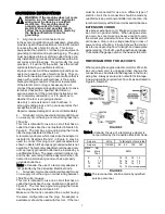
Страница 7: ...self and the spring engages the slot at the end of the guard post 5 Check the guard for proper tension If guard does not spring back into place when pulled back from cutterhead remove guard and adjust spring tension by repeating steps 1 3 until correct tension is achieved NEVER run the jointer without the guard being in place and in perfect working order INSTALLING DUST CHUTE Mount the dust chute ...

Страница 8: ... grounded outlet is not available The temporary adapter should be used only until a properly grounded outlet can be installed by a qualified electrician The green colored rigid ear lug and the like extending from the adapter must be con nected to a permanent ground suchas a properly grounded outlet box Note In Canada the use of a temporary adapter is not permitted by the Canadian Electrical Code 3...

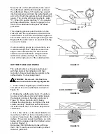
Страница 9: ...mately at the correct depth of cut 3 Turn the locking handle C until it is snug then fine tune the adjustment with the height adjustment handle D by rotating it until the scale reads exact Clockwise raises the table counterclockwise lowers the table NOTE The fine adjustment handle has 1 16 travel per rotation 4 When set retighten screw B To adjust outfeed table 1 Loosen thumbscrew E 2 Turn handwhe...

Страница 10: ...Slide the knife out until it is flush with the end of the shop scale Set the knife locking gib 1 32 inch in from the end of the knife Figure 14 WARNING Set the knives no more than 015 inches above the body of the cutterhead to minimize the hazard of kickbackand severe personal injury Snug the two outside gib locking screws If you have a knife setting gauge place it on the outfeed table and 0 the i...

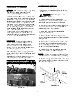
Страница 11: ...at t he high point o f the cutterhead arc OUTFEED TABLE AND KNIVES The outfeed table must be set exactly level with the knives at the highest point of their revolution Knives must also be parallel to the outfeed table To check alignment FIGURE 16 FIGURE 17 WARNING Disconnect machine from è power source before making alignments 1 Place a steel straightedge on outfeed table and extend it over the cu...

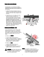
Страница 12: ...d wipe off any excess Securely tighten each screw which holds the knife inserts before operating the jointer Make sure all knife insert screws are tightened securely Loose inserts can be propelled at high speed from a rotating cutterhead causing injury FIGURE 19A CUTTERHEAD REMOVAL If removal of the cutterhead is necessary do the following WARNING Disconnect jointer from power source 1 Remove the ...

Страница 13: ...s FIGURE 20 FIGURE 21 1 Remove the cutterhead guard 2 Place a metal straightedge across both tables as shown in Figure 21 and make sure both tables are set to the exact height of the high point of the knives 3 Clamp a block of wood across the infeed table as shown in Figure 22 in order to block the end of a fine India stone or oilstone during the jointing opera tion This helps to prevent kickback ...

Страница 14: ...ghten the lock screws FENCE ADJUSTMENTS TILT Fence adjustments are made with the lock handles shown in Figure 24 To slide the fence forward or back on the table loosen lock handle A slide the fence to the desired position and tighten handle A to secure fence To tilt the fence forward 1 Loosen locking bolt B Figure 24 2 Place a machinist protractor or triangle on the table and against the fence Adj...

Страница 15: ...able and against the fence to confirm a 90º setting A Fig 25 6 If the fence is not square to the table release the lock handle J loosen the hex nut F and turn the stop bolt E until the fence is square to the table 7 Tighten the lock nut F to retain the setting Tighten the lock handle J FIGURE 24A FIGURE 25 FIGURE 25 FIGURE 25 45º Fence Backward Stop Adjustment Referring to Figure 26 The 45º fence ...

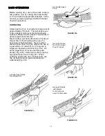
Страница 16: ...er surface pieces shorter than 12 inches or thinner than 3 8 inch without the use of a special work holding fixture Never surface pieces thinner than 3 inches without the use of a push block On stock 8 to 12 long use a single two handed push block Fig 27a On stock longer than 12 inches use two push blocks Fig 27b With narrow stock use the type push block shown in Fig 27c When surfacing short stock...

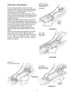
Страница 17: ... 28b Before the left hand is in the 3 inch area of the cutterhead move it over to the outfeed side Fig 28c As soon as possible follow with the right hand over to the outfeed side and continue through with cut Fig 28d Begin by feeding stock with right hand and apply pres sure to front of stock with push block When the stock is longer than twice the length of the infeed and outfeed tables another he...

Страница 18: ...beveled is over 12 inches long more than 1 4 inch thick and 1 inch wide Set fence to desired angle CAUTION Although fence may be tilted in FIGURE 29 FIGURE 30a è or out for bevel cut Sunhill Machinery recommends for safety reasons the fence be tilted in if possible making a cradled cut Fig 30a For wood wider than 3 inches hold with fingers close together near the top of the stock lapping over the ...

Страница 19: ... the fence to the fence support see page 4 Remove the fence 2 Remove the key from the fence slide base 3 Replace the fence assembly at the desired angle across the cutterhead Secure the fence to the sup port with the two hex nuts and flat washer then tighten the fence locking handle PUSH BLOCKS Push blocks are simple yet necessary tools to assist the operator especially when jointing thin or short...

Страница 20: ...19 PARTS DIAGRAMS ...

Страница 21: ...20 ...

Страница 22: ...21 ...

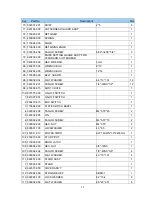
Страница 23: ...102 FLAT HD SOC SCREW 5 16 18NC 1 5 8 1 16 050031 000 FENCE 1 17 360676 901 STUD PIVOT 2 18 009010 200 HEX NUT 1 2 20NF 19 05B 11 11H 2 19 290004 901 BOLT SHOULDER 10 6 1 20 130007 903 NUT PIVOT 1 21 130008 903 NUT HANDLE 1 22 170598 901 STOP FENCE 1 23 009008 200 HEX NUT 7 16 14NC 17 4B 9 52H 1 24 009005 200 HEX NUT 5 16 18NC 12 7B 6 75H 2 25 003003 208 HEX SCREW 5 16 18NC 1 3 4 1 26 360035 902 S...

Страница 24: ...INING RING ETW 12 2 9 230013 901 SET SCREW 5 10 380066 000 GIB 2 11 050734 000 TABLE OUTFEED 1 12 190011 901 COLLAR 1 13 006004 086 FLAT WASHER 11 5 16 0 5t 1 14 130011 903 CLAMP 1 15 360037 000 SCREW ELEVATION 1 16 051123 000 TABLE INFEED 1 17 050083 000 BASE 1 18 360056 901 SHAFT 1 19 170101 901 FIXED PLATE 1 20 170102 901 TILT PLATE 1 21 290035 901 STUD PIVOT 1 22 360058 901 GUARD POST 1 23 130...

Страница 25: ...0NC 3 8 2 5 050018 901 BEARING HOUSING 1 6 920153 000 KNIFE LOCK BAR ASS Y 3 7 210006 000 KNIFE 3 8 030206 000 BALL BEARING 6202 2NSE 1 9 012003 009 KEY 5 5 25 1 10 030207 000 BALL BEARING 6203 2NSE 1 11 050019 901 BEARING HOUSING 1 12 050020 901 PULLEY 1 65 2 922855 000 SHEARTEC 2 CUTTERHEAD ASS Y 1 1 922856 000 SHEARTEC 2 CUTTERHEAD 1 2 850587 000 HARDWARE BAGE FOR SHEARTEC 2 1 038201 702 TORX S...

Страница 26: ...50036 615 DUST CHUTE 1 100 937575 000 ON OFF SWITCH 1 1 841007 001 ON OFF SWITCH 1 2 250479 615 BOX SWITCH 1 3 170694 902 PLATE SWITCH BEZEL 1 4 000302 209 PAN HD SCREW M4 0 7P 25 2 5 380332 905 PIN 1 6 000302 203 PAN HD SCREW M4 0 7P 10 2 7 008002 200 HEX NUT M4 0 7P 2 8 006501 100 LOCKWASHER 4 3 8 5 2 101 453011 013 POWER CORD SJT 14AWG 3C 2400mm 1 104 230010 000 STUD PIVOT 1 105 110005 000 DOOR...

Страница 27: ...03 203 HEX SCREW 5 16 18NC 3 4 4 120 014102 000 V BELT A36 1 121 006307 100 LOCK WASHER 10 2 18 5 3 122 004902 101 SCREW HEX SER FI 3 8 16 3 4 3 8 16NC 3 123 009005 200 HEX NUT 5 16 18NC 1 137 172317 902 COVER 2 138 009102 200 HEX NUT 3 8 16NC 4 139 004001 101 LOCK KONB 5 16 18NC 3 4 2 140 250400 000 WHEEL 4 141 003005 206 HEX SCREW 3 8 16NC 2 1 2 4 142 003303 105 PAN HD SCREW 3 16 24NC 3 8 5 143 ...

Страница 28: ...cations subject to change Machines may be shown with optional accessories 2018 Laguna Tools Inc LAGUNA and the LAGUNA Logo are the registered trademarks of Laguna Tools Inc All rights reserved 2072 Alton Parkway Irvine CA 92606 Ph 800 234 1976 www lagunatools com ...

Отзывы: