


4.4.1. P
ROPORTIONAL CONTROL
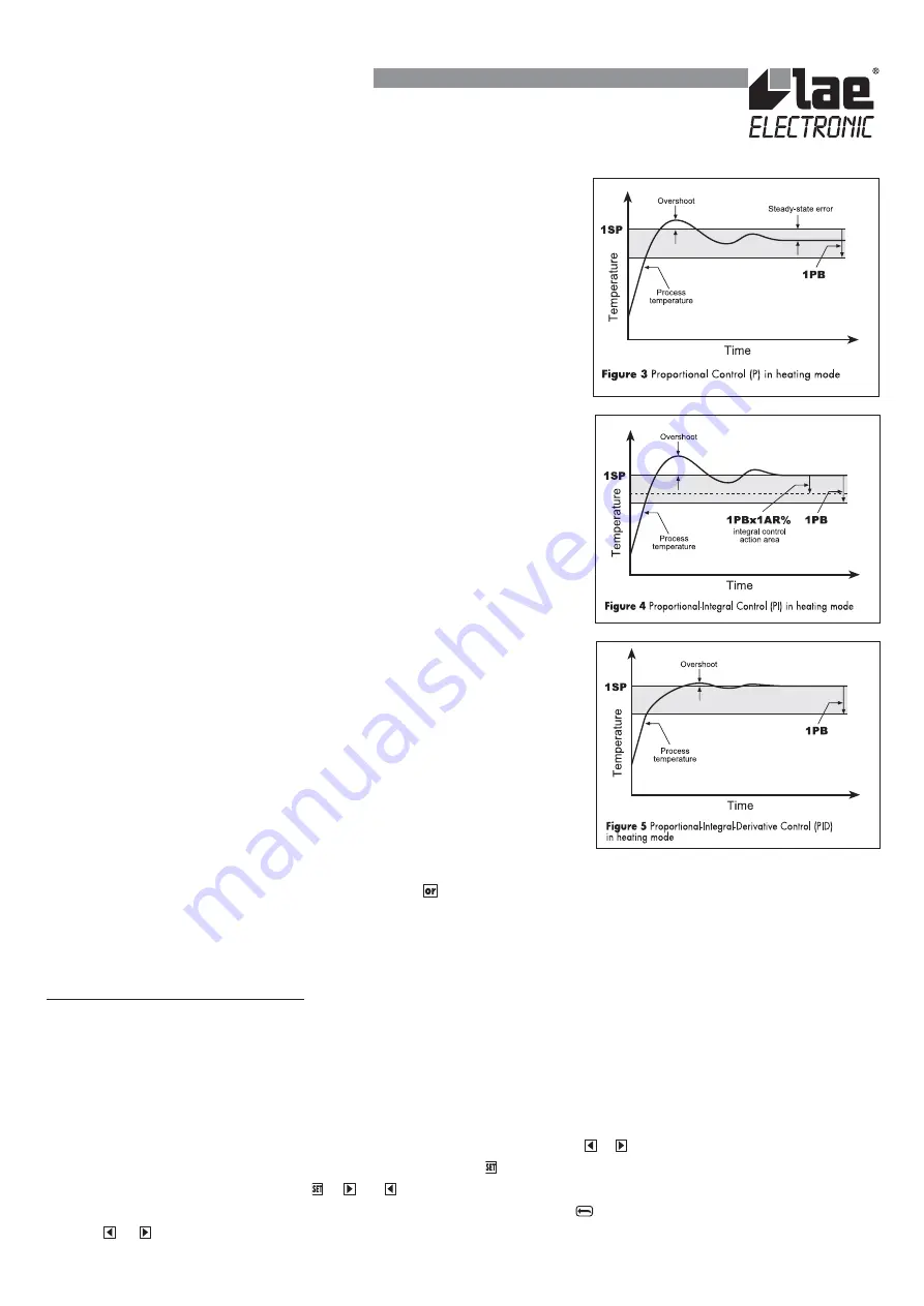
. The temperature is controlled by varying the time
of activation of the output when the temperature is inside the proportional band
(
1PB
). The nearer the temperature to set point, the less time of activation. A small
proportional band increases the promptness of response of the system to
temperature variations, but tends to make it less stable. A purely proportional control
stabilises the temperature within the proportional band but does not cancel the
deviation from the set point.
4.4.2. P
ROPORTIONAL
-
INTEGRAL CONTROL
. The steady-state error is cancelled by
inserting an integral action into the control system. The integral action time,
1IT
,
determines the speed of cancellation of the error, but a high speed (
1IT
low) may
be the cause of overshoot and instability in the response. The integral part normally
acts within the proportional band, but this area of action may be reduced in terms
of percentage by lowering the integral action reset
1AR
. The response overshoot is
thus decreased. The integral control is cancelled when the temperature goes outside
the area of action of the integral part. With
1IT=0
the integral control is disabled.
4.4.3. P
ROPORTIONAL
-
INTEGRAL
-
DERIVATIVE CONTROL
.
Response overshoot in a
system controlled by a PI controller may be reduced by inserting a derivative action
in the control. The derivative action is greater the faster the temperature variation
within the time unit. A controller with a high derivative action (1
DT
high) is extremely
sensitive to small temperature variations and can make the system instable. With
1DT=0
the derivative control is disabled.
4.5. M
ALFUNCTIONING
.
Following a sensor malfunction,
appears on the display and the output is controlled according to the
value of the parameter
1PF
.
CAUTION:
when programming the hysteresis 1HY or the proportional band 1PB, it is advisable to consider the number of
switchovers that the relay will carry out and, if necessary, adapt the cycle time in order to limit the frequency of switchover.
5. AUTO-TUNING
5.1.
B
EFORE STARTING
. Before starting the auto-tuning procedure, ensure that the output has been set with PID control, the
proportional band has the sign corresponding to the required mode of operation (heating/cooling) and that the set point has been
fixed at the required value. The auto-tuning procedure is divided into two parts. In the first part, the operator has to characterise
the process to be controlled by fixing the cycle time. In the second, the controller acquires the responses of the system to certain
stresses for efficient adaptation of the control parameters.
5.2.
S
TARTING THE FUNCTION
. To access the auto-tuning function, keep the keys
+
pressed for 3 seconds. If the output is
in the PID mode (1Y=PID),
1CT
starts to blink on the display. Press
to confirm selection of the channel; the current parameter
value is displayed simultaneously. Using +
or , change the cycle time to characterise the dynamics of the process to be
controlled. In this first phase the auto-tuning function may be quit by pressing key
. The acquisition phase starts upon pressing
the keys
+
or after 30 seconds without touching the keyboard.
INSTRUCTIONS FOR INSTALLATION AND USE.