


70
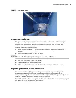
Tailgate and Body Maintenance
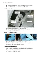
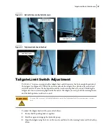
To adjust the body raised limit switch:
1.
Loosen the limit switch nut.
2.
Move the body to the approximate position where the switch is to be triggered. The warning
buzzer shall sound as soon as the body has reached a certain height above the chassis (usually
about 12 inches above the chassis).
3.
Tighten the nut.
4.
To fine tune the adjustment, loosen the nut slightly.
5.
With a flathead screwdriver, turn the adjusting screw located at the center of the nut until a click
is heard.
6.
Tighten the nut.
7.
Test the operation.
8.
If necessary, repeat steps 1 through 7.
Adjusting Body Partitions
The T
OP
S
ELECT
™ can be equipped with up to seven (7) air-operated opening body partitions, giving
eight (8) adjustable compartments for recyclable materials.
To adjust a body partition, do the following:
1.
Make sure the body is empty before performing this procedure.
2.
Apply the parking brake.
3.
Start the truck’s engine.
4.
Turn ON the hydraulic pump.
5.
Open the tailgate and set the tailgate safety prop (see
6.
Turn OFF the hydraulic pump.
7.
Stop the engine.
8.
Apply the Lockout/Tagout procedure (see
9.
Enter the body.
10.
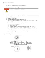
Slide off the partition’s top locking pin (see Figure 6
9).
11.
Release the floor locking pins using the manual locking-unlocking system (see Figure 6
10).
11 a.
Pull the lever to the left.
11 b.
Use the hook to block the lever.
Содержание Top Select
Страница 1: ...TOP SELECT TM MAINTENANCE MANUAL...
Страница 2: ......
Страница 3: ...TOP SELECT MAINTENANCE MANUAL...
Страница 8: ...vi Table of Contents...
Страница 34: ...26 Safety...
Страница 40: ...32 General Cleanliness...
Страница 72: ...64 Loading Container Maintenance...
Страница 104: ...96 Preventive Maintenance...
Страница 121: ...Lubrication 113 Figure 11 2 Body hinges Grease Fittings on Body Figure 11 3 Tailgate and hooks...
Страница 122: ...114 Lubrication Figure 11 4 Partition Figure 11 5 Optional Maximizer Location of lube zerks...
Страница 123: ...Lubrication 115 Figure 11 6 Roof hinges and loading cylinders...
Страница 124: ...116 Lubrication Figure 11 7 Lube chart...
Страница 132: ...124 Troubleshooting...
Страница 134: ...126 Hydraulic and Pneumatic Circuit Diagrams Hydraulic Schematics Single Side Bucket...
Страница 135: ...Hydraulic and Pneumatic Circuit Diagrams 127 Single Side Bucket w Maximizer...
Страница 136: ...128 Hydraulic and Pneumatic Circuit Diagrams Dual Side Bucket...
Страница 137: ...Hydraulic and Pneumatic Circuit Diagrams 129 Dual Side Bucket w Maximizer...
Страница 138: ...130 Hydraulic and Pneumatic Circuit Diagrams Dual Side Bucket w Maximizer and Dual Tailgate Cylinder...
Страница 139: ...Hydraulic and Pneumatic Circuit Diagrams 131 Air System Schematics TS 1000 w Options...
Страница 140: ...132 Hydraulic and Pneumatic Circuit Diagrams TS 2000 w Options...


