


78
Hydraulic System
•
Lifting arm section (up/down)
: proportional, no load sensor relief
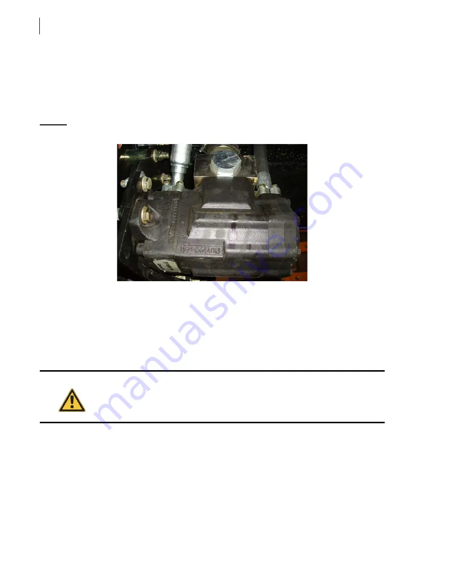
Inspecting the Pump
The hydraulic pump is powered by the vehicle engine through a drive shaft and a PTO. The pump
should be visually inspected every working day.
Figure 5-5 Pump
When inspecting the pump:
1.
Start the engine and engage the hydraulic pump.
The pump should turn freely without excessive noise or vibrations.
2.
Check for oil leaks under the pump and at connection points.
3.
Lock out and tag out the vehicle (see
Locking Out and Tagging Out the Vehicle
If electrical problems occured with the pump, see
Pump Replacement
It is important to apply the following procedure after making a pump replacement or a pump drive
shaft replacement.
For standard drive shaft, do the following:
1.
Locate the hole with the yoke bolt (the yoke must be fully engaged on shaft).
Caution!
If the unit has to be driven away for repairs on the hydraulic system (e.g. following
detection of an oil leakage), turn the PTO switch to the “OFF” position.
Содержание MINIMAX
Страница 1: ...MINIMAX TM MAINTENANCE MANUAL...
Страница 2: ......
Страница 3: ...MINIMAX MAINTENANCE MANUAL...
Страница 8: ...vi Table of Contents Adjusting Arm Speed 164...
Страница 30: ...22 Safety Figure 2 17 Drain valve on air tank...
Страница 72: ...64 Lubrication Figure 4 10 Lubrication chart Helping Hand arm...
Страница 80: ...72 Lubrication...
Страница 90: ...82 Hydraulic System Figure 5 8 Oil temp level gauge Figure 5 9 Steel hydraulic tank...
Страница 101: ...Hydraulic System 93 Figure 5 20 Hydraulic tank Access panel Return filter Strainer Suction line...
Страница 102: ...94 Hydraulic System Figure 5 21 Strainer assembly Strainer...
Страница 106: ...98 Hydraulic System Figure 5 25 Detecting cylinder internal leaks 1 2 3 4 5 A A A...
Страница 108: ...100 Hydraulic System...
Страница 113: ...Electrical System 105 Electrical Schematics Cab Adaptation...
Страница 114: ...106 Electrical System Cab Console Controls...
Страница 115: ...Electrical System 107 Cab Controller...
Страница 116: ...108 Electrical System Chassis...
Страница 117: ...Electrical System 109 Body Module rear side...
Страница 118: ...110 Electrical System Body Module front side...
Страница 119: ...Electrical System 111 Tailgate Lighting...
Страница 120: ...112 Electrical System Panic Bars Crusher Panel Tipper Interlocks...
Страница 121: ...Electrical System 113 Cameras Switchpack Details Interlocks AUTO 10 SEC INHIBIT AUTO N AUTO ON...
Страница 122: ...114 Electrical System...
Страница 127: ...Troubleshooting 119 Figure 8 4 Ball end hex wrench metric and SAE...
Страница 134: ...126 Troubleshooting Figure 8 6 Tailgate locking mechanism...
Страница 156: ...148 Multiplexing...
Страница 162: ...154 Multiplexing...
Страница 164: ...156 Lifting Arm Figure 10 1 Mounting bolts Figure 10 2 Helping Hand gripper Figure 10 3 Hoses...