


General Maintenance
27
4.
Fully open the tailgate by pressing the T
AILGATE
U
P
switch on the multiplexed control module
5.
Fully extend the packer by pressing the green P
ACK
button on the control packer station
6.
When the packer has reached its fully extended position, press the red E
MERGENCY
S
TOP
button
on the control packer station (see Figure 3-10).
7.
Install the tailgate safety prop.
8.
Perform the lockout/tagout procedure (see
Locking Out and Tagging Out the Vehicle
Inspecting the Packer
Proceed this way during the packer inspection:
1.
Inspect the follower panel hinges and surface in search of any wear or damage.
2.
Check for any sideways or up-and-down movement of the packer and inspect the wear pads
(plastic strips) on both sides of the packer.
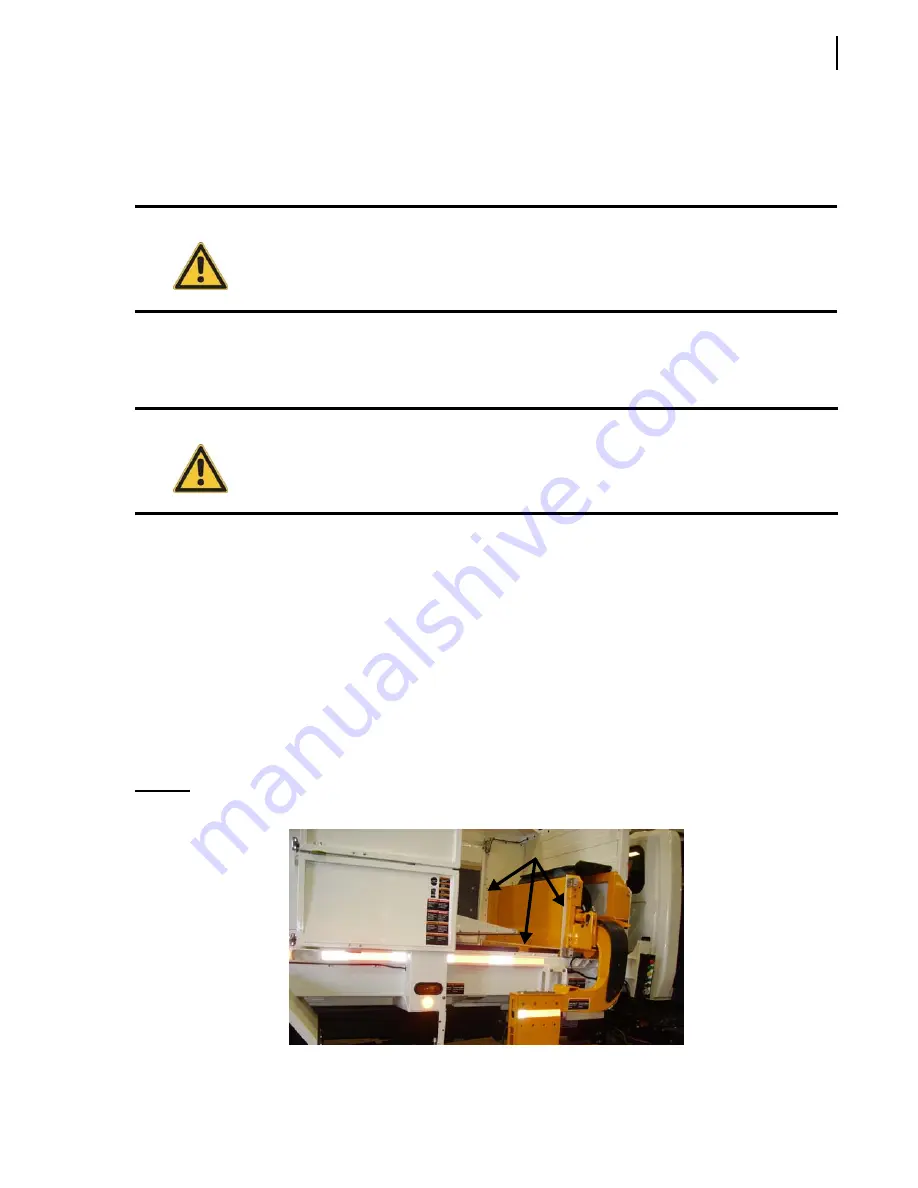
3.
Inspect the cover wear pads. These wear pads act as additional protection against intruding refuse
that may get inside the automated arm mechanism, where they can damage the cylinder and the
limit switches (see Figure 3-4).
Figure 3-4 Protective wear pads
4.
Inspect both body side rails and packer rollers for any premature wear (see Figure 3-3).
Danger!
Never enter the hopper while the packer is moving.
Danger!
Always use the tailgate safety prop while working under a raised tailgate. The safety prop
should be used even if the tailgate is in fully raised position.
Содержание MINIMAX
Страница 1: ...MINIMAX TM MAINTENANCE MANUAL...
Страница 2: ......
Страница 3: ...MINIMAX MAINTENANCE MANUAL...
Страница 8: ...vi Table of Contents Adjusting Arm Speed 164...
Страница 30: ...22 Safety Figure 2 17 Drain valve on air tank...
Страница 72: ...64 Lubrication Figure 4 10 Lubrication chart Helping Hand arm...
Страница 80: ...72 Lubrication...
Страница 90: ...82 Hydraulic System Figure 5 8 Oil temp level gauge Figure 5 9 Steel hydraulic tank...
Страница 101: ...Hydraulic System 93 Figure 5 20 Hydraulic tank Access panel Return filter Strainer Suction line...
Страница 102: ...94 Hydraulic System Figure 5 21 Strainer assembly Strainer...
Страница 106: ...98 Hydraulic System Figure 5 25 Detecting cylinder internal leaks 1 2 3 4 5 A A A...
Страница 108: ...100 Hydraulic System...
Страница 113: ...Electrical System 105 Electrical Schematics Cab Adaptation...
Страница 114: ...106 Electrical System Cab Console Controls...
Страница 115: ...Electrical System 107 Cab Controller...
Страница 116: ...108 Electrical System Chassis...
Страница 117: ...Electrical System 109 Body Module rear side...
Страница 118: ...110 Electrical System Body Module front side...
Страница 119: ...Electrical System 111 Tailgate Lighting...
Страница 120: ...112 Electrical System Panic Bars Crusher Panel Tipper Interlocks...
Страница 121: ...Electrical System 113 Cameras Switchpack Details Interlocks AUTO 10 SEC INHIBIT AUTO N AUTO ON...
Страница 122: ...114 Electrical System...
Страница 127: ...Troubleshooting 119 Figure 8 4 Ball end hex wrench metric and SAE...
Страница 134: ...126 Troubleshooting Figure 8 6 Tailgate locking mechanism...
Страница 156: ...148 Multiplexing...
Страница 162: ...154 Multiplexing...
Страница 164: ...156 Lifting Arm Figure 10 1 Mounting bolts Figure 10 2 Helping Hand gripper Figure 10 3 Hoses...