


390
Lifting Arms
Cylinder Cushion Adjustment
The tipper and extension cylinders are cushioned at the end of their strokes to give a smoother
movement. The cushioning speed is adjustable directly on the cylinders using two adjustment screws.
If the gripper or the arm hits hard at the end of its strokes, apply the following procedure.
Tipper Cylinder Cushioning Adjustment:
1.
Secure the arm working area using barrier tape or barricades.
2.
Put the transmission in neutral.
3.
Start the engine and engage the hydraulic pump.
4.
Fully extend the automated arm to access the arm tipper cylinder from the top (see Figure
15).
5.
Run the gripper arm for a full up/down cycle to determine if the amount of cushioning has to be
adjusted.
6.
If an adjustment is necessary, stop the hydraulic pump and turn OFF the engine.
N
OTE
:
To be able to make the necessary adjustment, the temperature of the hydraulic oil must be
around 140° F.
7.
Tighten the corresponding adjustment screw to obtain a smoother movement at the end of the
stroke or loosen the screw if the movement is too slow (no shock should occur).
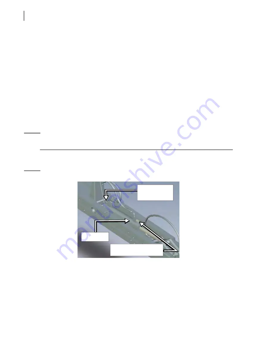
Figure 10
-
15 Cushioning adjustment screw (tipper cylinder)
Inner rail cylinder cushioning adjustment:
1.
Secure the arm working area using barrier tape or barricades.
2.
Put the transmission in neutral.
3.
Start the engine and engage the hydraulic pump.
4.
Run the arm for a full extent/retract cycle to determine if the amount of cushioning has to be
adjusted.
Tipper
cylinder
Gripper down cushioning
adjustment screw
Gripper up
cushioning
adjustment screw
Содержание EXPERT
Страница 1: ...EXPERT TM MAINTENANCE MANUAL...
Страница 2: ......
Страница 3: ...EXPERT MAINTENANCE MANUAL...
Страница 10: ...viii Table of Contents...
Страница 18: ...8 Introduction...
Страница 244: ...234 General Maintenance...
Страница 251: ...Lubrication 241 Figure 4 11 Glass compartment lubrication chart optional...
Страница 252: ...242 Lubrication Figure 4 12 EXPERT lubrication chart...
Страница 261: ...Lubrication 251 Figure 4 27 Packer lubrication points 2 Grease fitting LH side front cylinder pin...
Страница 263: ...Lubrication 253 Pump Drive Shaft U Joint Figure 4 30 Pump drive shaft lubrication points Grease fittings...
Страница 264: ...254 Lubrication...
Страница 320: ...310 Hydraulic System...
Страница 357: ...Troubleshooting 349...
Страница 358: ...350 Troubleshooting...
Страница 386: ...378 Multiplexing...
Страница 388: ...380 Lifting Arms Figure 10 1 Mounting bolts Figure 10 2 Wear pads Figure 10 3 Helping Hand gripper...


