background image

MHP Operating & Maintenance Manual 

15

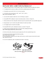
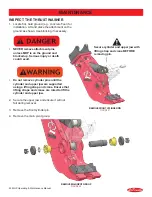
SWIFT-LOCK TEETH MAINTENANCE

When the jaw teeth are worn or cracking, performance is decreased and the teeth need to be replaced.

Removing the Upper Teeth

1. 

Locate flat, hard ground and place the attachment 

on the ground. 

2. 

Remove the washers, on each sides of each 

tooth, using a grinder.

Note: The washers are welded into place.

3.  Use a soft metal drift and a mallet to drive out the 

tooth pin.

4.  Remove the tooth from the receptacle.

Note: The retainer ring may fall out when removing the 

teeth. Do not lose the retainer ring.

5.  Insert the retainer ring in its place and insert a 

new Swift-Lock tooth.

6.  Insert the tooth pin and weld the washers in place.

Note: Insert the tooth pin so that the pin groove will 

line up and seat in the retainer ring.

Removing the Lower Tooth Platen

1.  Remove (6) M30 cap screws from the bottom of 

the lower jaw. Do not reuse the cap screws.

2. 

Remove the Lower Tooth Platen.

Note:  There  are  3  dowel  pins  press  fit  into  the  Lower 

Tooth Platen for positioning. Insert new dowels into the 

new Lower Tooth Platen.

3.  Install a new Lower Tooth Platen. Apply Loctite 

262 to the installation bolts and torque to 1350 ft. 

lbs. (1850 Nm).

•  Wear personal protection equipment at all 

times. This includes eye protection, hard hat, 

steel toe shoes, leather gloves and hearing 

protection.

•  Swift-Lock Teeth are very heavy. DO NOT 

remove a tooth pin if the tooth is not 

supported. The tooth may fall and cause injury.

MAINTENANCE

SWIFT-LOCK TEETH REMOVAL

Figure 16


SWIFT-LOCK 

TEETH

TOOTH PIN

RETAINER 

RING

WASHER

LOWER TOOTH 

PLATEN

TOOTH 

RECEPTACLE

Содержание MHP 200

Страница 1: ...Part Number 514990 4 2019 Ver 7 CE Operating and Maintenance Manual MHP SERIES MOBILE HYDRAULIC PULVERIZER...

Страница 2: ...etion at any time WARRANTY All work or repairs to be considered for warranty reimbursement must be authorized by the LaBounty Service Department before work is started Any alterations modifications or...

Страница 3: ...cal Specifications 11 Attachment Controls 11 Bleed the Hydraulic Cylinder 12 Operating Tips 12 Maintenance 13 Swift Lock Teeth Maintenance 15 Lubrication 16 Inspect Torque Bolts 17 Check for End Play...

Страница 4: ...tool or part is not specifically recommended by LaBounty determine whether it is safe for you and others and that the equipment will not be damaged or made unsafe as a result of your decision to imple...

Страница 5: ...ne Keep clear at a minimum of 15 feet 5 meters DO NOT close the attachment on a structure and reverse the excavator in an attempt to pull down material Avoid tipping The attachment will alter the lift...

Страница 6: ...operation DO NOT come in contact with hot hydraulic oil as it could cause severe burns Wear adequate protective clothing and safety equipment DO NOT tamper with hydraulic lines or components while the...

Страница 7: ...TEN FRONT CYLINDER PIN REAR CYLINDER PIN MAIN PIVOT GROUP SAFETY FIRST DECAL P N 503590 INCLUDED WITH MANUALS Figure 5 GREASE DECAL AT EACH FITTING P N 116388 Figure 6 Keep 75 feet 23m away when opera...

Страница 8: ...ufacturer s recommended procedure Note When removing the excavator bucket plug hydraulic hoses to prevent contamination THIRD MEMBER INSTALLATION 3 Remove the arm connection and link connection pins a...

Страница 9: ...50 250 LPM 4500 5500 PSI 310 380 Bar 1 Code 62 Flange MHP 350 50 110 GPM 190 416 LPM 4500 5500 PSI 310 380 Bar 1 Code 62 Flange 1 Connect hydraulic hoses from the base machine to the connections on MH...

Страница 10: ...anders clear especially before moving the boom swinging the upper structure or traveling ALWAYS be alert for bystanders in or near the operating area Safety Devices Seat belts Canopies Safety decals S...

Страница 11: ...JAWS CLOSE OPEN Figure 15 TECHNICAL SPECIFICATIONS Model Weight Jaw Opening Jaw Depth Lower Width Reach Max Pressure Max Flow Cycle Time Max Flow Minimum Excavator Size MHP 200 4850 Lbs 2200 Kg 37 in...

Страница 12: ...retract the excavator cylinder to it s limits Check for interference between the attachment and the excavator boom or stick Check the hydraulic lines that connect to the attachment Ensure they are no...

Страница 13: ...tings _________ Inspect bolts and fittings on attachment and jaws see Inspect Torque Bolts on page 17 Inspect connecting pins and retaining hardware _________ Arm Connection _________ Link connection...

Страница 14: ...NANCE 1500 HOUR INSPECTION CHECKLIST Inspect Thrust Washer _________ Inspect thrust washer Replace if necessary See Inspect the Thrust Washer on page 22 Inspected By __________________________________...

Страница 15: ...te Insert the tooth pin so that the pin groove will line up and seat in the retainer ring Removing the Lower Tooth Platen 1 Remove 6 M30 cap screws from the bottom of the lower jaw Do not reuse the ca...

Страница 16: ...tings are indicated on the attachment by yellow GREASE decals Each grease fitting requires 3 oz 8 g of grease This is about 6 shots of grease from an average grease gun MAINTENANCE MHP LUBRICATION POI...

Страница 17: ...55 Nm 49 ft lbs 67 Nm M12 71 ft lbs 96 Nm 85 ft lbs 116 Nm M14 112 ft lbs 152 Nm 136 ft lbs 185 Nm M16 173 ft lbs 235 Nm 207 ft lbs 281 Nm M20 335 ft lbs 454 Nm 403 ft lbs 547 Nm M24 579 ft lbs 785 N...

Страница 18: ...blade using 500 ft lbs 680 Nm torque on each bolt Stay at least 75 ft 23 m when moving 5 Cycle the jaws closed Measure the gap between the upper and lower blade using a feeler gauge If the gap is lar...

Страница 19: ...spirator Do all work in a well ventilated area CHECKING AND REPLACING WEAR PLATES Wear bars are welded into the jaw and must be replaced after they have worn down to 1 4 their original thickness Using...

Страница 20: ...and 7 until the tooth profile matches the build up template 9 Grind edges square to match the template 10 Using AWS E7018 place underlayment passes as shown in Figure 25 11 Apply a bead of Amalloy 81...

Страница 21: ...sing There are two screws you can use to control this speed change the Main Spool Adjustment Screw and the Pilot Valve Adjustment Screw Testing the Speed Valve Close the jaws and observe the movement...

Страница 22: ...ath could result Do not remove cylinder pins until the cylinder and upper jaw are supported using a lifting strap and crane Ensure that lifting straps and cranes are rated to lift the cylinder and upp...

Страница 23: ...er if the thickness is less than 0 355 inches REASSEMBLY AND SHIMMING 1 Slowly position the upper jaw into place Ensure the thrust washer is in place 2 Install the main shaft 3 Install the left and ri...

Страница 24: ...shim thickness from Figure 31 2 Install shims on the right hand side of the pivot group 3 Install the right hand end cap Apply Loctite 242 to the cap screw threads 4 Using a crane slowly open and clos...

Страница 25: ...ened Back pressure is too high in the base machine return line Use larger diameter hydraulic lines to minimize back pressure Move the main spool adjustment screw clockwise in small increments until th...

Страница 26: ......

Страница 27: ......

Страница 28: ...ing your dealer or the LaBounty parts department and requesting a CE Operation Maintenance manual You must include the attachment model number and serial number LaBounty 1538 Highway 2 Two Harbors Min...

Отзывы: