2. Hardware Description
The external features of the LabJack U12 are:
•
USB connector,
•
DB25 digital I/O connector,
•
Status LED,
•
30 screw terminals.
The USB connection provides power and communication. No external power supply is needed.
The +5 volt connections available at various locations are outputs, do not connect a power
supply.
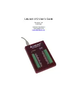
Figure 2-1. LabJack U12 top surface.
Figure 2-1 shows the top surface of the LabJack U12. Not shown is the USB and DB25
connector, which are both on the top edge. The DB25 connector provides connections for 16
digital I/O lines, called D0-D15. It also has connections for ground and +5 volts. All
connections besides D0-D15, are provided by the 30 screw terminals shown in Figure 1. Each
individual screw terminal has a label, AI0 through STB.
The status LED blinks 4 times at power-up, and then blinks once and stays on after
enumeration (recognition of the LabJack U12 by the PC operating system). The LED also
blinks during burst and stream operations, unless disabled. The LED can be enabled/disabled
through software using the functions AISample, AIBurst, or AIStreamStart. Since the LED uses
4-5 mA of current, some users might wish to disable it for power-sensitive applications.


