


108
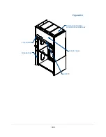
LINER TOP
REFERENCE
BRACE,
HARDWARE
& HARDWARE
COVERS
LOWER PERFORATED
BAFFLE
LOWER MIDDLE
PERFORATED BAFFLE
UPPER MIDDLE
BAFFLE
SMALL UPPER
BAFFLE
Baffle Installation
Be sure the baffles are resting in the proper baffle mount supports. The upper baffles
require a small baffle connected to a large baffle via a brace, hardware, and hardware
covers. See Figures E-3 and E-4 for installation location of each baffle size
.
Header Installation
Locate the header in protective packaging on the third skid. To install, the header is
fastened to the corner covers by four #12 screws. From behind the corner posts on the
side and install the screws to support the header. See Figure E-5. Now reinstall the side
panels of the upper cabinet.
Filter Installation
where filter installation is detailed for this step. For easier
installation, remove bracket(s) in front of the shafts with a nut driver before installing
filters. Replace brackets once the filters are connected prior to operating the filtered
hood.
Front Panel Installation
To install the front panel, hang the two plastic cylinders on the top of the front panel
over the corner posts. The bottom of the front panel will then slip behind the header
once it has been properly secured at the top. See Figure E-5.
Figure E-4
Содержание Protector Airo
Страница 78: ...78 Fans and Lights not working ...
Страница 79: ...79 Vertical sash no longer operates smoothly ...
Страница 80: ...80 Electrical duplex outlets no longer have power Fan operates but lights dim or not working ...
Страница 81: ...81 Contaminates outside the filtered hood ...
Страница 82: ...82 Lights operate but fans will not ...
Страница 83: ...83 Smart Command Alarms ...
Страница 84: ...84 If needed contact Labconco to troubleshoot further ...
Страница 88: ...88 1 2 3 4 5 6 7 8 9 10 13 12 11 14 15 19 22 23 24 26 25 27 28 20 18 REFERENCE SERIAL TAG Figure A 1 ...
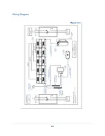
Страница 94: ...94 Wiring Diagram Figure C 1 ...
Страница 109: ...109 Figure E 5 TYPICAL NEUTRODINE FILTRATION TECHNOLOGY 12 SCREWS CORNER POST FRONT PANEL HEADER ...


