


14
IPX Series
Quick Start Guide
15
CAUTION! Whe n connecting wiring to Speaker Terminals,
the installation shall be made by an instructed person or
ready-made leads or cords shall be used
.
Bridge Mode
The IPX Series employs an inherently bridged Class D output topology.
CAUTION! Under no circumstances should the IPX Amplifier
be bridged, this may cause undesired operating
performance.
DSP configuration
Default configuration
IPX Series amplifiers are shipped with default DSP settings that allow immediate
use in many common applications with no need for further DSP configuration.
The default mode is suited for use with the stereo program into full range
loudspeakers.
The default signal routing and parameter settings are as follows:
• Analog 1 and AES1: Routed to Ch. 1
• Analog 2 and AES 2: Routed to Ch. 2
• AES3 to analog failover: OFF
• Mode: Stereo
• Input levels: 0 dB
• Input EQ: Flat
• Output levels: 0 dB
• Output Mute: Muted
• Output EQ: Flat
• Delay: Off
• Crossover: Off
Input connections
Analog Inputs
Analog inputs are available on two standard female XLR latching connectors.
The inputs are electronically balanced. The impedance is 20 kΩ, and the inputs
can accept a maximum input level of +26 dBu.
Polarity is as follows:
Pin 1 = screen (shield), pin 2 = positive (+), pin 3 = negative (-).
Analog Links
Two latching male XLR connectors are adjacent to the analog input connectors
and are paralleled to the input connectors to provide an unprocessed analog
loop-through to feed additional IPX Series units or other equipment.
AES3 Inputs
A latching female XLR connector accepts an AES3 digital audio signal. Input
impedance is 110 Ω. (Ensure that 110 Ω digital audio cables are used; standard
XLR microphone cables are rarely suitable for reliable digital audio transmission.)
AES3 is a stereo digital format, and therefore both inputs are fed via a single
connector. Selection of the analog or digital inputs is made via the front panel
display or IPX Controller software.
AES3 Link
A latching male XLR connector is fitted adjacent to the AES3 input connector.
This is an active link which sends an unprocessed AES3 loop-thru to feed
additional IPX units. The design requires no termination load when the unit is
the last connected.
Output connections
Two types of power output connections are available on IPX Series amplifiers:
Neutrik speakON and binding post. The two types are connected in parallel.
Loudspeakers may be connected to both at the same time, but this is generally
not recommended as total impedance may be too low.
Binding Posts
Power outputs for loudspeaker connection are available on two fully enclosed
binding posts. Observe signal polarity as indicated.
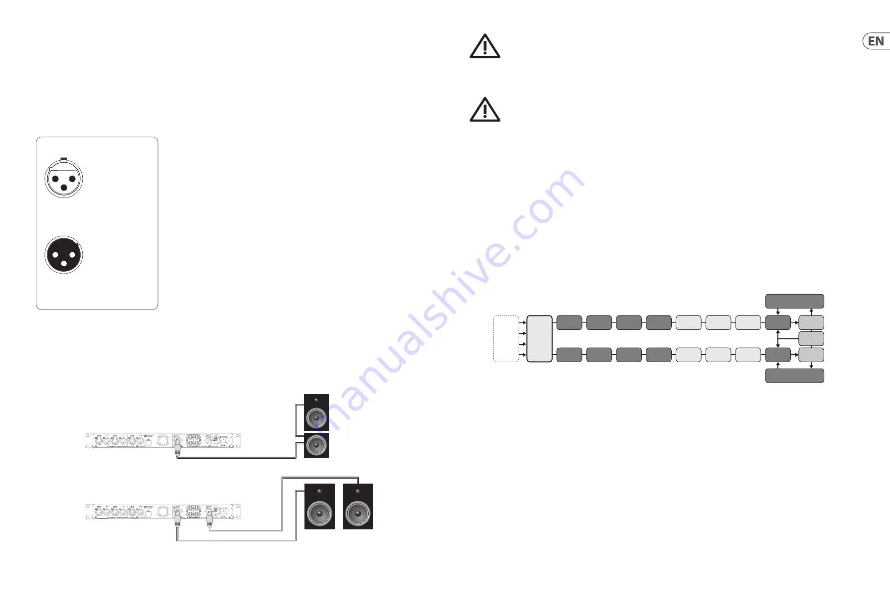
speakON Connectors
Outputs for both channel 1 and channel 2 are available on a four-pole speakON
connector to the left. The two-pole speakON to the right connect to output 2 only
(see Fig. 1 below). See the amplifier's back panel for information about the
available pin outs for speakON connection.
output
For unbalanced use, pin 1 and pin 3
have to be bridged
1 = ground/shield
2 = hot (+ve)
3 = cold (-ve)
input
1
2
3
1
2
3
Balanced use with XLR connectors
Fig. 1
Channel 1 sent
through to top box.
Channel 2
Channel 1 and 2
Channel 1
Signal flow block diagram
The block diagram below (Fig. 2) shows the signal flow from inputs to outputs
Fig. 2
Analog 1
Analog 2
AES 1
AES 2
Input 1
Levels
Input 1
EQ
Input 1
delay
Output 1
Levels
Output 1
EQ
IDEEA
Amplifier
Output 1
Delay
Clip Limiter
Clip Limiter
Rail Sense Limiter
SCVPL
X-Over
Input 2
Levels
Input 2
EQ
Input 2
delay
Output 2
Levels
Output 2
EQ
IDEEA
Amplifier
PSU
Output 2
Delay
SCVPL
X-Over
Input
Mixer
Содержание IPX Series
Страница 9: ......


