


=
pÉêîáÅÉ=j~åì~ä=pmUMc^=L=pmUMc_=
m~ÖÉ=O=ENUF
=
=
cìåÅíáçå~ä=ÇÉëÅêáéíáçå=Ñçê=ëïáíÅÜ=ãçÇÉ=éçïÉêëìééäó=pmUMc^=C=pmUMc_=
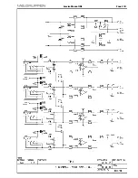
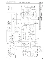
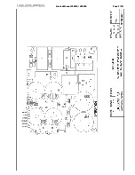
Theory of function
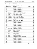
SP80FA-board:
AC-power is coming in to terminal P1, passing interference filter L1, L2 and then reaching RE1 and R5.
In some variants the on-off switch is located directly after terminal P1, in other variants it is connected to CP5-CP7, controlling
the soft start relay RE1. When the on-off switch turns in position CP5-CP6, soft start resistor R5 gives power to mains rectifier
D1.
The voltage is rectified by D1 and filtered by C8, C9 and C1, C2 (SP80FB). This gives 310V DC to the transformer.
SP80FB-board:
Current generator R17, D4, Q5, R16, R10 charge C9 until D3 conduct at 15V. Q8 work as under voltage protection for the +15V
voltage by turning U1:3 to 5V if U1:15 drops below 14V.
When U1:2 (under voltage protect) reach 3V soft start capacitor C10 (U1:8) is released, witch slowly increase the pulse width of
U1:12.
The PWM-controller U1:12 controls the switch Q1-Q3 to give the correct output voltage at terminal CP17, CP19 (SP80FA).
When the switch Q1-Q3 is closed, current flows trough transformer, storing energy. Because of the voltage polarity, diode D3,
D4 (SP80FA) are reverse-biased, thus no voltage present at the load. When the switch is open, the transformer reverses polarity
because of the collapsing magnetic field, forward-biasing diode D3, D4 and inducing a current flow into the capacitors C12, C14
(SP80FA).
If U1:3 (over voltage protect) goes above 3V the pulses on pin 12 stops immediately. This occurs if the main voltage is too high,
or the voltage across snubber capacitor C5 is too high.
The reversed voltage is sensed by a winding in the transformer and rectified by diode D8. The PWM-controller adjust the on-
time of the switch, by comparing the voltage across C14 (U1:17) with an internal reference (U1:16), to give the right rail voltage
across the capacitors C12, C14 (SP80FA). The voltage can be adjusted by potentiometer VR2.
The maximum current in the transformer is sensed over the resistor R6-R8. The voltage across R6-R8 is compared (U1:6) with a
reference-voltage, set by VR3, witch make it possible to adjust the maximum output power from the power supply. Normally
VR3 is in maximum position, but if something has to be repaired in the amplifier, VR3 is used for "slow starting" the amplifier.
SP80FA-board:
Immediately when Q1-Q3 (SP80FB) turn on, D2 rectify the pulse from the transformer (CP11, CP12). The DC voltage across C7
activates RE1 witch short soft start resistor R5.
To turn off the amplifier the on-off switch is set in position CP6-CP7. This disconnects R5, and open RE1, turning the amplifier
off.
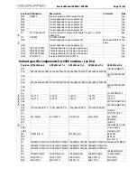
Repairing instructions
REQUIRED MEASUREMENT EQUIPMENT:
-Audio generator
-Dummy load, 16 ohm
-Digital voltmeter
-Variac 0-280V, 6A
-50Mhz oscilloscope, ex. Tek 2225 with 100x probe ex. Tek P6009
-Isolation transformer for the mains, 1:1
1)
Turn VR3 (SP80FB) fully counter clockwise.
2)
Change FU1 (SP80FA).
3)
Increase the main voltage slowly by the variac.
4)
Measure the voltage across C8 and C9 (SP80FA).
a)
No voltage: -change R5 (SP80FA).
b)
The current increases quickly:
-check D1 (SP80FA).
Содержание fP Series FP 2400Q
Страница 3: ...p j mOQMMn m O EQF f...
Страница 7: ...p j MQ_ L MU_ m O ENMF p MQ_I MU_...
Страница 8: ...p j MQ_ L MU_ m P ENMF _ MQ_...
Страница 9: ...p j MQ_ L MU_ m Q ENMF _ MU_...
Страница 17: ...p j fkQ m O ERF p fkQ...
Страница 18: ...p j fkQ m P ERF _ fkQ...
Страница 21: ...p j iaRQ m N ERF LD54 Schematics for LD54 2 Board placement for LD54 3 Component list for LD54 4x6 2 rev 01 4...
Страница 22: ...p j iaRQ m O ERF p iaRQ...
Страница 23: ...p j iaRQ m P ERF _ iaRQ...
Страница 26: ...p j lrqQ m N EQF OUT4 Schematics for OUT4 2 Board placement for OUT4 3 Component list for OUT4 A04B rev 01A 4...
Страница 27: ...p j lrqQ m O EQF p lrqQ...
Страница 28: ...p j lrqQ m P EQF _ lrqQ...
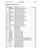
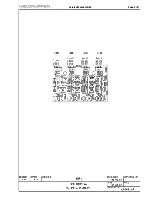
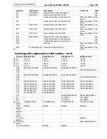
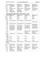
Страница 33: ...p j pmUMc L pmUMc_ m Q ENUF p pmUMc C pmUMc_...
Страница 34: ...p j pmUMc L pmUMc_ m R ENUF p pmUMc I pmUMc_ C mfka...
Страница 35: ...p j pmUMc L pmUMc_ m S ENUF pmUMc _ pmUMc J MQ...
Страница 36: ...p j pmUMc L pmUMc_ m T ENUF _ pmUMc J MS...
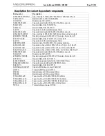
Страница 41: ...p j pmUMc L pmUMc_ m NO ENUF pmUMc_ _ pmUMc_ C mfka...


