LAARS Heating Systems
Page 16
Size
20°F
(11°C)
25°F
(14°C)
30°F
(17°C)
35°F
(19°C)
gpm
lpm
gpm
lpm
gpm
lpm
gpm
lpm
500
43
161
34
129
26
107
24
92
750
64
241
51
193
43
161
36
138
1000
85
321
68
257
57
214
49
184
1250
106
401
85
322
71
269
61
231
1500
128
483
102
386
85
322
73
276
1750
N/R
N/R
119
451
99
375
85
322
2000
N/R
N/R
103
515
113
429
97
368
Notes:
gpm = gallons per minute,
lpm = liters per minute
,
Maximum temperature rise is 35°F (19°C), as shown.
N/R = not recommended.
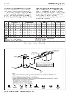
Table 8. Temperature Rise - Boiler.
SECTION 4A.
Water Connections —
Pennant Boiler
4A.1 Heating System Piping:
Hot Supply Connections — Boiler
NOTE:
This appliance must be installed in a closed
pressure system with a minimum of 12 psig (82.7
kPa) static pressure at the boiler.
Hot water piping should be supported by suitable
hangers or floor stands. Do not support piping with
this appliance. Due to expansion and contraction of
copper pipe, consideration should be given to the type
of hangers used. Rigid hangers may transmit noise
through the system resulting from the piping sliding in
the hangers. It is recommended that padding be used
when rigid hangers are installed. Maintain 1" clearance
to combustibles for hot water pipes.
Pipe the discharge of the relief valve (full size)
to a drain or in a manner to prevent injury in the event
of pressure relief. Install an air purger, an air vent,
a diaphragm-type expansion tank, and a hydronic
flow check in the system supply loop. Minimum fill
pressure must be 12 psig (82.7 kPa). Install shutoff
valves where required by code.
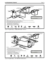
See suggested piping diagrams (
Figures 4-5).
These diagrams are meant only as a guide. Com pon-
ents required by local codes must be properly installed.
Note the recommended location of the
temperature sensor on the diagrams; you must provide
a location for the additional sensor shipped with the
Pennant. This sensor may be strapped onto pipe from
1" to 4" diameter, or inserted into an immersion well.
4A.2 Cold Water Make-Up — Boiler
1. Connect the cold water supply to the inlet
connection of an automatic fill valve.
2. Install a suitable back flow preventer between the
automatic fill valve and the cold water supply.
3. Install shut off valves where required.
NOTE:
The boiler, when used in connection with a
refrigeration system, must be installed so the chilled
medium is piped in parallel with the boiler with
appropriate valves to prevent the chilled medium from
entering the boiler.
The boiler piping system of a hot water heating
boiler connected to heating coils located in air
handling appliances where they may be exposed to
refrigerated air circulation must be equipped with flow
control valves or other automatic means to prevent
gravity circulation of the boiler water during the
cooling cycle.
A boiler installed above radiation level, or as
required by the authority having jurisdiction, must be
provided with a low water cutoff device either as a part
of the boiler or at the time of boiler installation.
4A.3 Water Flow Requirements — Boiler
Low Temperature Pennant Boilers are equipped
with a mounted pump. The pumps are sized for the
boiler’s head loss and 30 feet of full-size piping (same
size as boiler outlet), with a normal number of fittings.
The boilers must be piped in a primary-secondary sys-
tem, such that the boiler’s pump only serves the boiler.
Figures 4 and 5
show examples of this type of piping.
The minimum inlet water temperature to the
Pennant is 70°F (20°C). The mixing system on the
Pennant will ensure that the heat exchanger in the
Pennant does not see water that is less than 120°F
(49°C), so that excessive condensation does not form
on the heat exchanger.
Table 8
shows a relationship between water flow
through the boiler and the temperature difference (rise)
between the inlet and outlet of the boiler. This table
will enable the user to test the boiler for proper water
flow. Since the boiler has a mixing system that sends
a portion of the hot water from the boiler outlet to the
boiler inlet, the water flow coming out of the mixing
system will vary, depending on the return water
temperature.
4A.4 Freeze Protection — Boiler
Boiler installations are not recommended in
areas where the danger of freezing exists unless proper
precautions are made for freeze protection. A non
toxic, heating system, anti-freeze may be added to the
hydronic system provided that the concentration does
not exceed 50% and the anti freeze contains an anti
foamant. Power outage, interruption of gas supply,
failure of system components, activation of safety
devices, etc., may prevent a boiler from firing.
Any
time a boiler is subjected to freezing conditions,
and the boiler is not able to fire, and/or the water
is not able to circulate, there is a risk of freezing in
the boiler or in the pipes in the system.
When water
freezes, it expands. This can result in bursting of pipes
in the system, or damage to the boiler, which could
result in leaking or flooding conditions.
IMPORTANT NOTES:
Different glycol products may
provide varying degrees of protection. Glycol products
must be maintained properly in a heating system, or
they may become ineffective. Consult the glycol speci-
fications, or the glycol manufacturer, for information
about specific products, maintenance of solutions, and
set up according to your particular conditions. Never
use
ethylene
glycol (automotive antifreeze).
Содержание Pennant PNCH
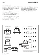
Страница 23: ...Low Temperature Pennant Page 23 Figure 12 Ladder Diagram Sizes 500 1000 ...
Страница 24: ...LAARS Heating Systems Page 24 Figure 13 Ladder Diagram Sizes 1250 2000 ...
Страница 25: ...Low Temperature Pennant Page 25 Figure 14 Wiring Diagram Sizes 500 1000 ...
Страница 26: ...LAARS Heating Systems Page 26 Figure 15 Wiring Diagram Sizes 1250 1500 ...
Страница 27: ...Low Temperature Pennant Page 27 Figure 16 Wiring Diagram Sizes 1750 2000 ...


