LAARS Heating Systems
TABLE OF CONTENTS
SECTION 1
Product Accessories
1.1 Introduction ...........................................................
1
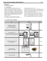
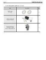
1.2 Included with the Appliance ................................
1-2
SECTION 2
Product Characteristics
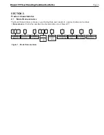
2.1 Model Nomenclature .............................................
3
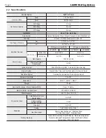
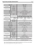
2.2 Specifications ........................................................
4
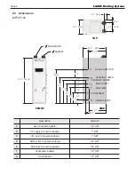
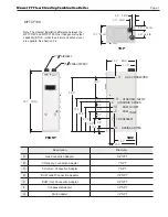
2.3 Dimensions ...........................................................
6
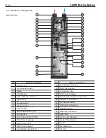
2.4 Names of Components .........................................
8
2.5 Product Flow and Characteristics .......................
10
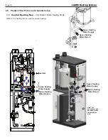
2.5.1 Central Heating Flow ..................................
10
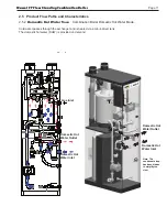
2.5.2 Domestic Hot Water Flow...........................
11
SECTION 3
Safety Regulations
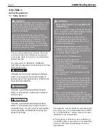
3.1 Safety Symbols ...................................................
12
3.2 Safety Precautions and Proper Use ....................
14
SECTION 4
Installation
4.1 Location and Clearances .....................................
16
4.2 Wall Mount Bracket ..............................................
17
4.2.1 Installation Height and Location .................
17
4.2.2 Hang the Boiler ..........................................
17
4.3 Combustion Air .....................................................
18
4.3.1 Combustion Air from Room ........................
18
4.3.2 Ducted Combustion Air ..............................
18
4.4 Venting (exhaust) .................................................
20
4.5 General Location Guidelines ................................
21
4.6 Locations for Vent Pipe Terminator ......................
23
4.6.1 Direct Venting Clearances ..........................
23
4.6.2 Non-Direct Venting Clearances ..................
24
4.6.3 Venting Requirements in Massachusetts ...25
4.7 Air Supply and Vent Connections at the Appliance .
26
4.7.1 Vent / Air Pipe Lengths ...............................
26
4.7.2 Direct Venting .............................................
26
4.7.3 Indoor Combustion Air ................................
27
4.8 Vent / Air Pipe Termination ...................................
27
4.9 Gas Supply and Piping .........................................
29
4.10 Gas Supply Pressure ..........................................
32
4.11 Gas Set Up and Adjustment ................................
32
4.12 High Altitude Installations and Orifices ................
33
4.13 Natural Gas to Propane Conversion ...................
34
4.14 Plumbing Guideline .............................................
38
4.15 Pressure Relief Valves ........................................
42
4.16 Disposal of Condensate ......................................
43
4.17 Electrical Wiring Connections ...........................
44
4.18 DIP Switches .................................................... 45
4.19 Control Board, Electrical Diagram .....................
47
4.20 Ladder Diagram ................................................
48
4.21 Electrical Connections ......................................
49
SECTION 5
Control Display and Operation
5.1 Control Dial and Buttons ......................................50
5.2 LCD Overview ......................................................51
5.3 Operating Mode ................................................. 52
5.4 Status Display Mode ......................................... 53
5.5 DHW Set Point Change Mode ........................... 54
5.6 CH Set Point Change Mode .............................. 55
5.7 Storage Mode .................................................... 55
5.8 Installer Mode .................................................... 56
5.9 Outside Temperature (option) ............................ 58
5.10 External Set Point Temperature Control ............ 58
5.11 Error Mode ........................................................ 59
SECTION 6
Error Codes
6.1 Error Codes .......................................................
60
6.2 Fault Tree Analysis ............................................
63
SECTION 7
Trouble Shooting
7.1 Diagnostics ........................................................ 65
7.2 Suggested Corrective Actions ...........................
67
SECTION 8
Maintenance
8.1 Annual Startup and General Maintenance ........
68
8.2 Flushing or Draining ..........................................
70
SECTION 9
Installation Check
9.1 Quick View ........................................................
71
9.2 Final Check Lists ...............................................
72
SECTION 10
Repair Part Diagrams
10.1 Parts List and Illustrations ............................ 74-85
Содержание MFTCF140
Страница 48: ...LAARS Heating Systems Page 46 4 19 Control Board Electrical Diagram SECTION 4 Installation...
Страница 65: ...Mascot FT Floor Standing Combination Boiler Page 63 6 2 Fault Tree Analysis 1 Flame detection...
Страница 75: ...Mascot FT Floor Standing Combination Boiler Page 73...
Страница 78: ...LAARS Heating Systems Page 76 Heat Exchanger MFTCF140...


