

LAARS Heating Systems
Page 8
commencing within 12” (300 mm) of the top and
one commencing within 12” (300 mm) of the
bottom, of the enclosure shall be provided. The
openings shall communicate directly, or by ducts,
with the outdoors or spaces that freely communicate
with the outdoors. when directly communicating
with the outdoors, or when communicating to the
outdoors through vertical ducts, each opening shall
have a minimum free area of 1 square inch per
4000 Btu/hr (550 square mm/kw) of total input
rating of all equipment in the enclosure. when
communicating to the outdoors through horizontal
ducts, each opening shall have a minimum free
area of not less than 1 square inch per 2000 Btu/
hr (1100 square mm/kw) of total input rating of all
equipment in the enclosure.
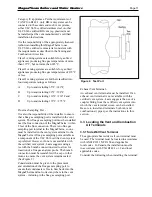
Method 2
: One permanent opening, commencing
within 12” (300 mm) of the top of the enclosure,
shall be permitted. The opening shall directly
communicate with the outdoors or shall
communicate through a vertical or horizontal duct
to the outdoors or spaces that directly communicate
Section 3
VentInG anD ComBUStIon aIr
3.1
Combustion air
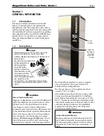
MagnaTherm boilers and water heaters must have
provisions for combustion and ventilation air in
accordance with the applicable requirements for
combustion Air Supply and Ventilation in the
National Fuel Gas Code, ANSI Z223 1; or in Canada,
the natural Gas and Propane installation code, cSA
B149.1. All applicable provisions of local building
codes must also be adhered to.
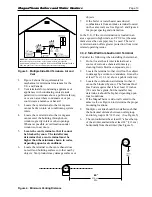
A MagnaTherm can take combustion air from the
space in which it is installed, or the combustion
air can be ducted directly to the unit. Ventilation
air must be provided in either case.
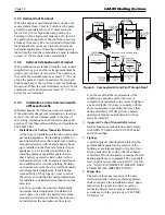
3.1.1
Combustion air from room
in the United States, the most common requirements
specify that the space shall communicate with the
outdoors in accordance with Method 1 or 2. (See the
following descriptions.) where ducts are used, they
shall be of the same cross-sectional area as the free
area of the openings to which they connect.
Method 1
: Two permanent openings, one
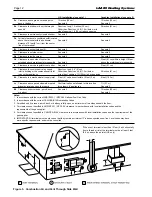
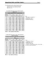
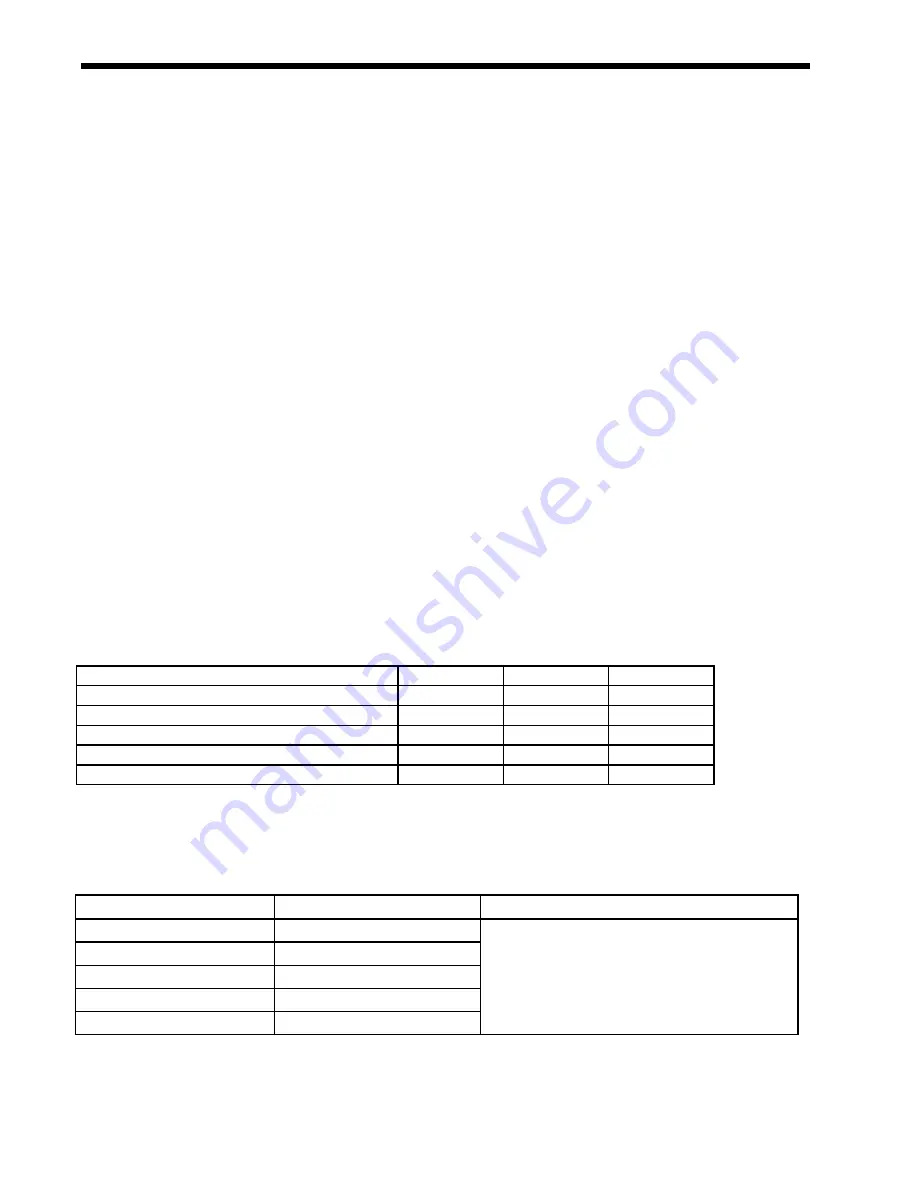
table 3. Ducted air accessories
(Place in section 3.1)
Model 2000
Model 3000
Model 4000
Screen for horizontal galvanized air pipe
D2012101
D2012102
D2012103
Screen for horizontal PVC air pipe
CA012001
CA012002
CA012003
Screen for horizontal polypropylene air pipe
CA012201
CA012202
CA012203
Screen for vertical galvanized air pipe
D2012201
D2012202
D2012203
Screen for vertical PVC air pipe
CA012401
CA012402
CA012403
Screen for vertical polypropylene air pipe
CA012601
CA012602
CA012603
Table 3a - Ducted Air Accessories
(Place in section 3.2)
Model 2000
Model 3000
Model 4000
Horizontal vent terminal for stainless steel
D2012001
D2012002
D2012003
Screen for horizontal CPVC vent
CA012101
CA012102
CA012103
Screen for vertical stainless steel vent
D2012301
D2012302
D2012303
Screen for vertical CPVC vent
CA012501
CA012502
CA012503
Table 3* - Vent Accessories
(Place in section 3.5)
Model 2000
Model 3000
Model 4000
Air intake screen for unit placed outdoors
CA011901
CA011902
CA0011903
Vent terminal for unit placed outdoors
CA011801
CA011802
CA011803
Table 3** - Air & Vent Accessories for Units Placed Outdoors
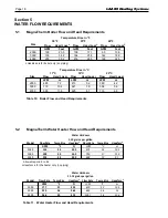
table 4. required Combustion air Pipe material
Material
United States
Canada
ABS
ANSI/ASTM D1527
The air pipe material must be chosen based upon
the intended application of the boiler, and must
be installed according to the vent manufacturer’s
installation instructions.
PVC, sch. 40
ANSI/ASTM D1785 or D2665
CPVC, sch. 40
ANSI/ASTM F441
Single wall galv. steel
26 gauge
Polypropylene
ULC S636 Class 2C


