(P/N)738.098 Rev A • 04/09
© copyright 2009
Kaba Mas LLC
page 3 of 5
ENTRY DEVICE MOUNTING
STANDARD METHOD
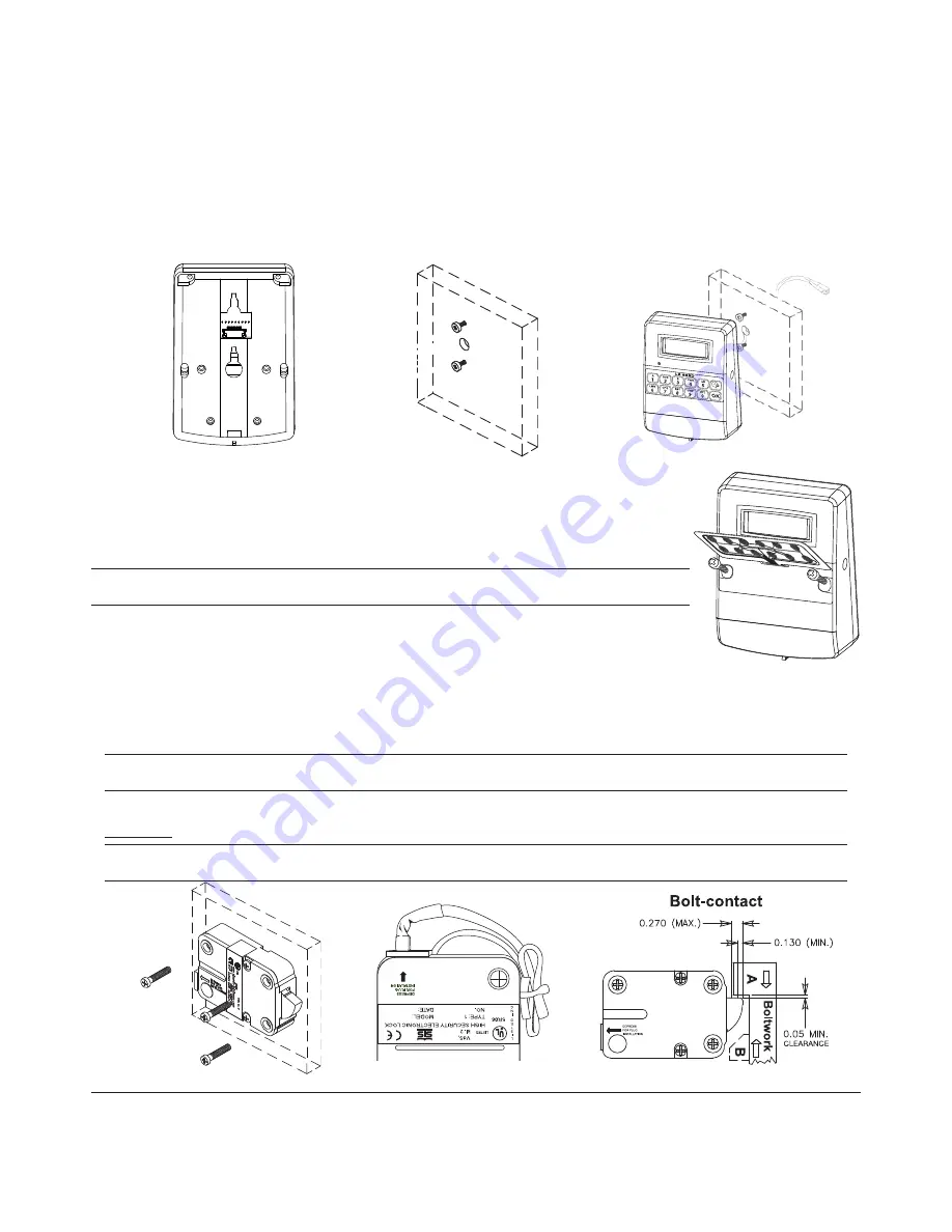
The 8130 Entry Device comes with a backplate for ease of mounting. (Figure 1)
1. Locate, drill and tap holes to mount the Entry Device to the outside of the safe door using the installation template provided.
2. Install the two #8-32 shoulder screws (US) or the two M4-0.7 shoulder screws (Metric) on the front of the safe door to mount the
Entry Device to the door. (Figure 2)
3. Feed the Entry Device cable through the spindle cable hole from the front of the safe door. (Figure 3)
4. Position the slotted holes on the backplate of the Entry Device over the mounting screws and then slide the Entry Device down onto
the mounting screws.
5. Remove the adhesive strip from the back of the keypad and carefully align before adhering to the housing.
ALTERNATE METHOD (TAMPER EVIDENT FOR VdS APPROVAL)
The 8130 Entry Device comes with the mylar portion of the keypad unattached. (Figure 4)
1. Locate, drill and tap holes to mount the Entry Device to the outside of the safe door using the
installation template provided.
2. Feed the Entry Device cable through the spindle/cable hole from the front of the safe door.
3. Install the two M4-0.7 Phillips screws through the front of the housing to mount the Entry Device to
the door. (Figure 4)
Warning:
Before completing the next step, you should ensure that the jumper switches for time delay/
open window are set as desired.
4. Remove the adhesive strip from the back of the keypad and carefully align before adhering to the
housing.
LOCK CONNECTION AND MOUNTING
SWING BOLT
1. Locate, drill and tap holes to mount the Lock Assembly to the inside of the safe door using the
installation template provided.
2. Ensure that the Entry Device cable is running through the channel at the back of the lock. Mount the lock with
the three US 1/4
"
-20 (Metric M6X1) screws.
Note:
All four mounting orientations are possible. The recommended torque for mounting screws on the Swing bolt lock is 30
in./lbs. for the US 1/4"-20 screws (3.4 N•m for Metric M6X1). (Figure 5)
3. Secure any cables with wire tie, making sure to keep out of the way of all moving parts. (Figure 6)
4. The blocking part “A” of boltwork should exert pressure on the entire width of the lock bolt. In the locked position the boltwork
MUST NOT
place pressure on the lock bolt.
Note:
In case of boltwork construction where two blocking parts are moving opposite one another, the one facing the round side
of the lock bolt “B” should be cut off to avoid jamming of lock bolt. (Figure 7)
Figure 1
Figure 2
Figure 3
Figure 5
Figure 6
Figure 7
Figure 4


