background image

ESI-2000

Pilot’s Guide

2-4

Basic operation


The barometric pressure has a range of between 27.00 and 32.00 in. Hg. or 
914 and 1083 for hPa or mb.


The last change to the baro value will be saved 

to memory and applied at power-up. 

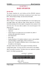
BARO ADjUSTMENT (Refer to Figure 2-6)

When  selected  in  the  menu  window  the  current  barometric  pressure  is 
shown. The baro value can be changed as follows: 

A single press of the 

+/-

 buttons increases or decreases the baro 

value by 0.01 inches of mercury “in. Hg” or by 1 for “hPa” or “mb”. 
Holding in the 

+/-

 buttons adjusts the baro value until released. 

A single press of the Select 

S

 button sets the baro value to the 

standard value of 29.92 in. Hg or 1013 hPa or mb. 


BARO UNITS ADjUSTMENT (Refer to Figure 2-5)

When selected in the menu window the current barometric unit is shown. 

Press of the 

+/-

 buttons to change the baro unit selection from/to 

one of the following units: “in. Hg”, “hPa” or “mb”.
The unit value changes in the baro window as the units are 
changed in the menu. 

Figure 2-6:  Baro Adjustment Menu

Figure 2-5:  Baro Unit Adjustment Menu

Содержание Trilogy ESI-2000

Страница 1: ...Pilot s Guide for the Electronic Standby Indicator Avionics Systems Model ESI 2000 Software Release 1 x ...

Страница 2: ......

Страница 3: ...bject to U S Patents existing or applied for L 3 Communications Avionics Systems Inc reserves the right to add improve modify or withdraw functions design modifications or products at any time without notice L 3 Communications Avionics Systems Inc 5353 52nd Street S E Grand Rapids MI 49512 USA Customer Support 800 453 0288 International 616 949 6600 FAX 616 977 6898 www l 3avionics com Pilot s Gui...

Страница 4: ...n in Standby Instrumentation The Trilogy Electronic Standby Instrument ESI is a panel mounted solid state instrument that provides dependable backup for attitude altitude and airspeed information for Part 23 25 Fixed Wing Aircraft and Part 27 29 Rotorcraft The Trilogy ESI 2000 replaces traditional electro mechanical standby instruments and combines the information into a compact and easy to read 4...

Страница 5: ... Alignment 2 2 Baro Units Adjustment 2 4 Baro Adjustment 2 4 Status Screen 2 5 Battery Capacity Meter Calibration Procedure 2 6 Chapter 3 Operating Instructions 3 1 Introduction 3 1 Power On 3 1 Self Test 3 1 Cycle Power Instructions 3 1 Power Off 3 2 System Identification 3 3 Alignment 3 3 Normal Operation 3 4 Pre Flight Instructions 3 5 Menu Settings 3 5 Instrument Check 3 5 In Flight Instructio...

Страница 6: ... Figure 3 3 Alignment Screen Not In Flight 3 3 Figure 3 4a Display Elements for part 27 29 Aircraft 3 4 Figure 3 4b Display Elements for part 23 25 Aircraft 3 4 Figure 3 5 De cluttered Display in Extreme Roll 3 6 Figure 3 6 De cluttered Display in Extreme Pitch 3 6 Figure 3 7 Display Showing Menu Window 3 7 Figure 3 8 Display Ascending Right Bank 3 7 Figure 3 9 Display Descending Left Bank 3 8 Fig...

Страница 7: ...trix Liquid Crystal Display AMLCD with a nominal diagonal size of 3 7 inches and a resolution of VGA 320 X 240 RGB Flicker free operation is obtained with a 60 Hz refresh rate combined with a minimum 30 Hz update rate A bezel mounted light sensor provides automatic dimming with manual offset controlled via the menu access mode Four soft key buttons on the front of the bezel provide the user with q...

Страница 8: ...1 2 New configuration option to receive heading information digitally from an external source New VG mode for Part 27 29 rotorcraft New display message to give pilot choice to perform alignment when a overrate condition is detected Provide wrapping functionality to non numeric Menu lists Attitude Fail is displayed when a problem is detected during alignment instead of waiting for alignment to comp...

Страница 9: ... Certification FAA and EASA TSO C2d Type B Part 23 25 40 to 400 kts Part 27 29 20 to 350 kts and for Release 1 1 Part 23 25 46 to 460 mph Part 27 29 23 to 403 mph C3e Type II Slip Only C4c C6e C10b 1 500 to 55 000 ft C46a C113 C179 ETSO C2d Type B Part 23 25 40 to 400 kts Part 27 29 20 to 350 kts and for Release 1 1 Part 23 25 46 to 460 mph Part 27 29 23 to 403 mph C3d Type II Slip Only C4c C6d C1...

Страница 10: ...e 1 1 1 2 Part 23 25 Aircraft 40 to 550 units Part 27 29 Rotorcraft 20 to 550 units Viewable Range Release 1 0 Part 23 25 Aircraft 40 to 400 kts Part 27 29 Rotorcraft 20 to 350 kts Release 1 1 1 2 Part 23 25 Aircraft 40 to 400 kts or 46 to 460 mph Part 27 29 Rotorcraft 20 to 350 kts or 23 to 403 mph Altitude Viewable Range 2 000 to 56 000 ft 610 to 17 000 m Heading Magnetic Heading ARINC 429 Relea...

Страница 11: ...lease 1 0 Part 23 25 Aircraft 40 to 400 kts Part 27 29 Rotorcraft 20 to 350 kts Release 1 1 1 2 Part 23 25 Aircraft 40 to 400 kts or 46 to 460 mph Part 27 29 Rotorcraft 20 to 350 kts or 23 to 403 mph Longitudinal Axis Acceleration 7 5 g Lateral Axis Acceleration 7 5 g Vertical Axis Acceleration 12 0 g BATTERY PERFORMANCE Capacity Typical 2 hours Minimum 1 hour when temperature is 15 C to 60 C 5 F ...

Страница 12: ...l readout at the bottom of the display Optional Equipment Figure 1 2a MAG 3100 Figure 1 2b MAG 3000 SCHEDULED MAINTENANCE Battery capacity meter requires automated calibration periodically Subject to requirements of FAA document CFR FAR Part 91 411 SERVICE LIFE The indicator has unlimited service life The battery has approximately 5 years of service life provided that the procedures for maintenanc...

Страница 13: ...e aircraft s pitch The scale has a maximum pitch of 80 A bullseye is shown at the 90 position of the pitch ladder Red V shaped chevrons appear on the pitch ladder when the unit is placed in extreme pitch See Figure 3 12 and 3 13 The chevrons point towards the horizon with the point of the chevron positioned at 35 50 and 65 sky background and 25 45 65 ground background Limitations When configured t...

Страница 14: ...ound the aircraft reference symbol boresight and has a roll angle range of 180 If the roll pointer is configured for rotating the roll pointer rotates around the aircraft reference symbol boresight and has a roll angle range of 180 Aircraft Reference Symbol refer to Figure 1 3 Located in the center of the attitude display the aircraft reference symbol is a fixed square boresight with L shaped wing...

Страница 15: ...rks at the midpoint between the major tick marks and numbered digits every 20 kts or mph from 20 to 540 kts or mph The calibrated range of the tape is from 20 to 350 kts 23 to 403 mph Slip Skid Indicator refer to Figure 1 3 The indicator has a black background with a white border A Slip Skid indicator ball is positioned in the center of the indicator scale between two vertical lines The Slip Skid ...

Страница 16: ...onfigured for Vmo Cues Vfe Vs1 Vs0 Vmc and Vyse may be configured off Part 27 29 Rotorcraft Airspeed Awareness Color Bar may be configured for Vne Power On Vne Power Off and Vcaution the start of the caution range for airspeed warning Cues Vne Power On and VCAUTION may be configured off Indicated Airspeed continued Airspeed Digital Readout refer to Figure 1 4 The odometer styled IAS digital readou...

Страница 17: ...ESI 2000 Pilot s Guide 1 11 Description Figure 1 5a IAS Awareness Bar Cues for Part 23 Aircraft using Vne Figure 1 4 IAS Elements Indicated Airspeed Continued ...

Страница 18: ...ESI 2000 Pilot s Guide 1 12 Description Figure 1 5b IAS Awareness Bar Cues for Part 23 25 Aircraft using Vmo Figure 1 5c IAS Awareness Bar Cues for Part 27 29 Rotorcraft Indicated Airspeed Continued ...

Страница 19: ...56 000 feet Configuration Option The tape background may be either clear or gray Barometric Pressure Window refer to Figure 1 6 Located at the top right of the display screen The value shown is used by the indicator to determine the current altitude Configuration Option The baro digits may be white cyan or green on a black background The units shown in the window can be changed using the menu scre...

Страница 20: ...is shown when altitude is less then zero Figure 1 6 Attitude Elements Metric Digital Readout refer to Figure 1 6 Configuration Option The MetricAltitude Digital Readout may be configured ON or OFF The Metric Digital Readout is located on the right side of the display beneath the odometer styled Altitude Digital Readout The readout has a black background surrounded by a white box with medium white ...

Страница 21: ...ing Digital Readout refer to Figure 1 7 The readout is located above the heading tape and displays the aircraft s current heading referenced to magnetic north The heading value has a range of 001 to 360 with a resolution of 1 The readout is removed whenever the menu window is opened Heading Index refer to Figure 1 7 Also known as lubber line the heading index is a fixed downward pointing arrowhead...

Страница 22: ...charge or charge and battery failure The following table provides a brief description and examples of common battery indicators Status messages provide details on battery calibration and how to continue operating the indicator using the backup battery During normal operation of the ESI 2000 unit powered by aircraft power and the battery has at least 1 hour of run time no battery indicator or messa...

Страница 23: ... ages the charging indicator remains amber at a SOC of 50 75 or 100 Availability Indicators The accuracy of the battery capacity meter may be degraded and requires a calibration discharge cycle Until a capacity calibration is performed the discharge function of the battery continues to work but the battery capacity is not available Battery operation discharge is not possible due to high temperatur...

Страница 24: ......

Страница 25: ...tion of power Baro Adjustment Baro Units Battery Shutdown The battery shutdown menu is only available when the battery is discharging Refer to Section 3 Battery Cal The battery calibration menu is only available when the battery is discharging Changes made to the menu items appear immediately after the change takes place The menu window is removed from the display after 5 seconds of inactivity The...

Страница 26: ...so be increased outside the menu window by pressing and holding the M button User Initiated Alignment Refer to Figure 2 3 and 2 4 When selected in the menu window pressing the Start S button will force the indicator to re align The attitude will align within 1 minute if the aircraft is on ground and stationary If a magnetometer is installed the heading reference will align to less than or equal to...

Страница 27: ... User Initiated Alignment continued Alignment Screen for Part 23 25 Aircraft Alignment Screen for Part 27 29 Aircraft NOTE Release 1 2 The heading tape and readout are available during alignment if the ESI 2000 is configured to receive external digital heading and heading data is valid ...

Страница 28: ... decreases the baro value by 0 01 inches of mercury in Hg or by 1 for hPa or mb Holding in the buttons adjusts the baro value until released A single press of the Select S button sets the baro value to the standard value of 29 92 in Hg or 1013 hPa or mb Baro Units Adjustment Refer to Figure 2 5 When selected in the menu window the current barometric unit is shown Press of the buttons to change the...

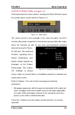
Страница 29: ...s screen similar to Figure 2 8 The status screen is only available in the menu list within the first 3 minutes after power is applied to the indicator and provides information about the indicator as well as any fault and installation problems detected during the Power On Self Test The unit Serial Number operating hours battery temperature and battery charge capacity are displayed on the System Sta...

Страница 30: ...ons or to accommodate temperature and time requirements The calibration procedure can take up to 8 hours to complete To assure compliance with the temperature limits of the calibration if performing the calibration procedure on aircraft the factory recommends in regions with hot climates performing the procedure during the cooler months of the year and in regions with cold climates performing the ...

Страница 31: ...2000 Remove external power from the ESI 2000 by placing the aircraft battery switch s OFF The ESI 2000 automatically switches over to battery power Press any button as stated by the message Press the M menu button and cycle through the menu options until Batt Cal see Figure 2 9 is located Press and hold the Hold button until the Battery Calibration screen is shown with the following message 1 2 3 ...

Страница 32: ...e battery is charged to greater than 95 SOC shut the ESI 2000 down for a rest period of 2 hrs for battery stabilization After the rest period reapply power and go to step 2 above When calibration is complete the ESI 2000 automatically powers down A 5 hr rest period is required for the battery calibration to be successful CAUTION APPLYING POWER TO THE ESI 2000 BEFORE THE END OF THE 5 HOUR REST PERI...

Страница 33: ...System Identification Alignment Normal Operation Self Test Application of power begins the indicators diagnostic of sensors circuitry memory and battery The self test lasts for approximately 15 seconds and during this time the display remains blank If no faults are detected the system identification splash screen is displayed Cycle Power Instructions Remove input power from the ESI 2000 Shut down ...

Страница 34: ...tinues to discharge for the entire 5 minutes When time is less than 30 seconds the messages change as shown below At the end of the 5 minutes the timer and press any key message are removed and the following message is shown as the ESI 2000 enters its shutdown mode The ESI 2000 can be manually shutdown only when in discharge mode using the following procedure Press any key button as stated by the ...

Страница 35: ...ve external digital heading and heading data is valid 1 2 Within 3 minutes of application of power the Aligning message and status bar are replaced by attitude display elements The attitude aligns to less than or equal to 1 of vertical in pitch and roll If the indicator is configured for a magnetometer and receiving heading information within 3 minutes of application of power the heading tape and ...

Страница 36: ...of the ESI 2000 provides attitude pitch and roll barometric corrected altitude metric altitude readout optional indicated airspeed slip skid indicator airspeed awareness cues and heading optional information Figure 3 4a Display Elements for part 27 29 Aircraft Figure 3 4b Display Elements for part 23 25 Aircraft ...

Страница 37: ...vailable NOTE Airspeed readout shows a white dash until aircraft exceeds 40 knots Part 23 25 Aircraft or 20 knots Part 27 29 1 2 Menu Settings Set brightness level Set barometric units displayed on Baro window Set barometric pressure NOTE Press the Menu M button to open the menu window Repeated pressing cycles the menu options Refer to Chap 2 Basic Operation for specific details Pre Flight Instruc...

Страница 38: ...ll pointer and airspeed configured for Vne Part 23 aircraft The display is shown in a Left bank 60 which has caused the heading information to be removed Chevrons are shown indicating extreme pitch In addition the airspeed awareness bar is in the caution range Figure 3 5 De cluttered Display in Extreme Roll Figure 3 6 De cluttered Display in Extreme Pitch NOTE The red low speed awareness is indica...

Страница 39: ... both Part 23 25 and Part 27 29 aircraft Notice how the roll scale has rotated in the same direction as the pitch ladder Figure 3 8 Display Ascending Right Bank Figure 3 7 depicts a display configured with heading rotating roll pointer metric altitude readout the baro color configured green and airspeed configured for Vne Part 23 aircraft The display is shown with the baro menu window active causi...

Страница 40: ... pitch with the airspeed awareness bar indicating a high speed warning Figure 3 10 Display at 90 degree Descent Figure 3 9 depicts a display configured with heading rotating roll pointer airspeed configured for Vne Part 23 aircraft and gray colored tape areas The display is shown descending while banking to the left with the airspeed awareness bar in the caution range Figure 3 9 Display Descending...

Страница 41: ...d Vmc with critical engine inoperative Figure 3 11 Display Showing Vmc Vyse Figure 3 12 depicts a display configured to show Part 27 29 Rotorcraft The display is shown ascending while banking to the left The Airspeed awareness bar is showing Vne Power On set to 160 Vne Power Off set to 130 see red white horizontal bar and the start of the caution range for airspeed warning Vcaution set to 150 Figu...

Страница 42: ...ading and attitude data is removed from the display When steady and level flight can be maintained press the menu M button twice followed by pressing the Select S button to begin re alignment Release 1 2 If the ESI 2000 rate of motion roll pitch or yaw exceeds 135 per second the heading and attitude remain working but a Cautionary Message is displayed giving the pilot the option to perform or not ...

Страница 43: ...en above the heading readout and slip skid indicator If the ESI 2000 is configured for a magnetometer as the heading reference then the following message is displayed if an overrate condition is detected and magnetic heading data is valid If the ESI 2000 is configured for a magnetometer as the heading reference then the following message is displayed if an overrate condition is detected and magnet...

Страница 44: ... Airspeed Loss Errors and Invalidities Continued Airspeed Configuration Data Loss Refer to Figure 3 15 If airspeed configuration data is lost the Airspeed Awareness Color Band is removed from the airspeed tape and a yellow SPD message is displayed adjacent to the airspeed tape Cycle power to the ESI 2000 if configuration data loss continues to be observed refer to Chapter 4 Troubleshooting Figure ...

Страница 45: ...e information and all attitude information is removed from the display replaced with a Attitude Fail message Cycle power to the ESI 2000 if invalidity continues to be observed refer to Chapter 4 Troubleshooting Figure 3 16 Altitude Loss NOTE Release 1 2 The heading tape and readout is available if the unit is configured to receive external digital heading and heading data is valid ...

Страница 46: ...state While the message is active and the ESI 2000 is configured for a magnetometer as the heading reference the heading readout is removed and the heading tape is filled with a red X Returning the aircraft to non dynamic straight and level flight will cause the Aligning message to return Figure 3 17 Align Hold NOTE Release 1 2 The heading tape and readout is available if the unit is configured to...

Страница 47: ...out is removed replaced by either a No Mag Input or Mag Failed message If magnetic heading data becomes valid the display elements automatically reset to normal operation A re alignment is recommended NOTE Release 1 0 1 1 The alignment menu select is not available while the heading is invalid for part 27 29 Rotorcraft If invalidity continues to be observed refer to Chapter 4 Troubleshooting Figure...

Страница 48: ... aligned the Align Hold message replaces the attitude information the heading tape is filled with a red X and the heading digital readout is removed replaced by either a No Mag Input or Mag Failed message If heading data becomes valid the unit completes alignment and normal operation begins If invalidity continues to be observed refer to Chapter 4 Troubleshooting Figure 3 20 Align Hold No Mag Inpu...

Страница 49: ... the heading tape is filled with a red X and the heading digital readout is removed replaced by either a No 429 Input or Inv 429 Input or 429 Failed message If heading data becomes valid the display elements automatically reset to normal operation A re alignment is recommended If invalidity continues to be observed refer to Chapter 4 Troubleshooting Figure 3 22 Heading Invalidity No 429 Input Figu...

Страница 50: ...ESI 2000 Pilot s Guide 3 18 Operating Instructions Figure 3 24 Heading Invalidity 429 Failed Errors and Invalidities Continued ...

Страница 51: ... returns to normal flight straight and level press the Menu M button twice and press the Select S button to align the indicator OR Indicates loss of airspeed altitude or atti tude data Cycle power to the ESI 2000 If the invalidity continues to be observed after power is cycled check the system status screen for a failure message If message is observed have ESI 2000 checked by certified service cen...

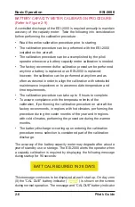
Страница 52: ...ast 5 sec onds Brightness of display should be ob served ESI 2000 may be defective Have ESI 2000 checked by certified service center BATT WORN OUT REPLACE message is displayed on screen during startup Message will be displayed at startup and remain on screen for 90 seconds The battery can no longer hold a state of charge greater than 1 hour and requires replacement Have ESI 2000 checked by certifi...

Страница 53: ...Cº 140Fº 2 If the Batt Temp temperature on this screen is NOT Amber indicating that the battery temperature is 60Cº 140Fº then the battery voltage is too low to operate Allow unit to continue to charge Battery discharge functionality returns to normal after the battery voltage in creases to the appropriate level Red X in place of Altitude OR Red X in place of Airspeed Indicates loss of data Cycle ...

Страница 54: ...f a Mag Failed message is shown above the heading tape then the Mag is sending a failure message If Mag begins working the message is removed and the heading tape and digital readout return If heading tape and readout do not become active cycle power to the Mag and the ESI 2000 If the invalidity continues to be observed after power cycle the Mag may be defective Have Mag checked by certified servi...

Страница 55: ...g normal operation after aligning is complete Version 1 2 only ESI 2000 configured for external heading source only One of the following conditions are de tected 1 If a No 429 Input message is shown above the heading tape then external 429 data is not being received If the LRU providing external heading input data begins working the message is removed and the heading tape and digital readout retur...

Страница 56: ...ome active cycle power to the ESI 2000 and the LRU provid ing external heading input data If the invalidity continues to be ob served after power cycle the LRU providing external heading input data may be defective 3 If a 429 Failed message is shown above the heading tape then the external heading data is invalid If the heading tape and readout do not become active cycle power to the ESI 2000 If t...

Страница 57: ... straight and level flight will cause the Aligning message to return 2 For Part 27 29 aircraft The Mag is sending a failed message This is in dicated by the heading digital readout being removed and a large red X in the middle of the heading tape A Mag Failed message is shown above the heading tape If Mag begins working the mes sage is removed and the align ment continues If the alignment does not...

Страница 58: ... does not become active cycle power to the Mag If the invalidity continues to be observed after power cycle the Mag may be defective Have Mag checked by certified service cen ter Screen is green If the screen input data fails to update the screen elements are removed and re placed with the green screen Cycle power to the ESI 2000 If the green screen continues to be ob served after power cycle the ...

Страница 59: ...eq Mag Swing Req Have ESI 2000 system checked by certi fied service center System Status Screen If one of the following messages appear Processor Fail Memory Fail Supply Fail Sensor Fail Calibration Req SSEC Data Fail VMax Data Fail Battery Fail ESI 2000 may be defective Have ESI 2000 checked by certified service center Corrective Actions continued ...

Страница 60: ......

Страница 61: ..._ Model Number______________________________________________ Part Number________________________________________________ Serial Number_______________________________________________ Mod Letter _________________________________________________ Release____________________________________________ Appendix A Aircraft Information Aircraft Make_______________________________________________ Aircraft Mod...

Страница 62: ...NC 429 release 1 2 Keybd ____ Altimeter Units Ft Ft M Airspeed Units kts mph release 1 1 1 2 AIRSPEED Part 23 Type Vne Part 23 25 Type Vmo Part 27 29 Rotorcraft Vne _____ Vmo _____ Vne power On _____ Vno _____ Vne power Off _____ Vfe _____ Vfe ______ Vcaution _____ Vs1 _____ Vs1 ______ Vs0 _____ Vs0 ______ Vyse ____ Vyse _____ Vmc ____ Vmc _____ Aircraft using SSEC Yes No release 1 2 Aircraft usin...

Страница 63: ...and Yaw panel angles must be determined at the time of initial installation MAG INSTALL Mounting Pitch _______ Roll _______ Yaw _______ Wing Flex Airspeed No Comp _______ Full Comp _______ Compensation Pitch _______ Roll _______ Installation Notes To be completed by the initial installer Notes ...

Страница 64: ...00 01 Rev E 03 25 2011 Avionics Systems BATTERY SYMBOL QUICK REFERENCE BATTERY INDICATOR DESCRIPTION Not Shown No information needs to be conveyed to pilot Green More than 1 hour of operation remains Amber Less than 1 hour of operation remains Amber X Battery is not available to power unit over temp or low battery voltage condition exists Red X Battery has failed ...

Отзывы: