


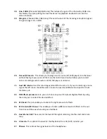


28. Stereo graphic equalizer.
This allows you to cut or boost certain frequencies to help
enhance the mix. The middle of each graphic is your 0dB starting point. Frequencies tend to
be cut or ‘notched out’ more than boosted. Ideal if you are in a room which does not have
particularly good acoustics. You can use the graphic to cut certain frequencies that
sometimes tend to feedback. There are 7 frequency bands on each graphic, ranging from a
low 125Hz to a high 8KHz.
29. L&R master sliders.
These control the main mix level to the left and right outputs.
30. Mono.
This provides a mono signal output which could be used to drive a Powered Sub.
31. Aux.
This controls the overall output of the auxiliary.
32. Aux
send.
This is used to connect to an input on a monitor or to send the signal if using an
external effects processor.
3
3. Eff send/foot sw.
This is used to send the signal to aux2/efx if using an external effects
processor or is used to defeat the internal effects
34. L&R stereo out.
These outputs are used if you wish to connect the mixer to an external
power
amplifier.
When these outputs are selected the internal power amps are by passed.
35. Phones.
Used for headphone monitoring. Activating the PFL switch on the channels enables
you to listen to the isolated channel. Deactivation enables you to listen to the main mix.
36. Mono
out.
Used to connect to an external power source, such as a sub bass bin for
example.
37. Level
display.
These are 3 stage LED indicators. Their primary function is to show you the
main output levels of both left and right outputs. The number indicators are in decibels
(dB). When in the green or yellow zone, this indicates that the main output is not being
overdriven. (Likewise when in PFL mode, which is measuring the channel input). Always aim
for the output to not exceed 0DB for any length of time. Try to avoid the LED’s spending too
much time in the red zone. This could damage speakers.
38. Power amp select.
This enables you to ‘bridge’ both internal amplifiers to give you a mono
sum. When bridge is used output connection should be made from the left output. Output
level will then be indicated by the left slider and meter.
Содержание PD1023
Страница 1: ...PD1023 Powered Mixer Owners Manual And Instruction Guide ...
Страница 3: ......