


Corrective maintenance
D/R - Grill
Tools
• torque screwdriver
• T25 Torx bit
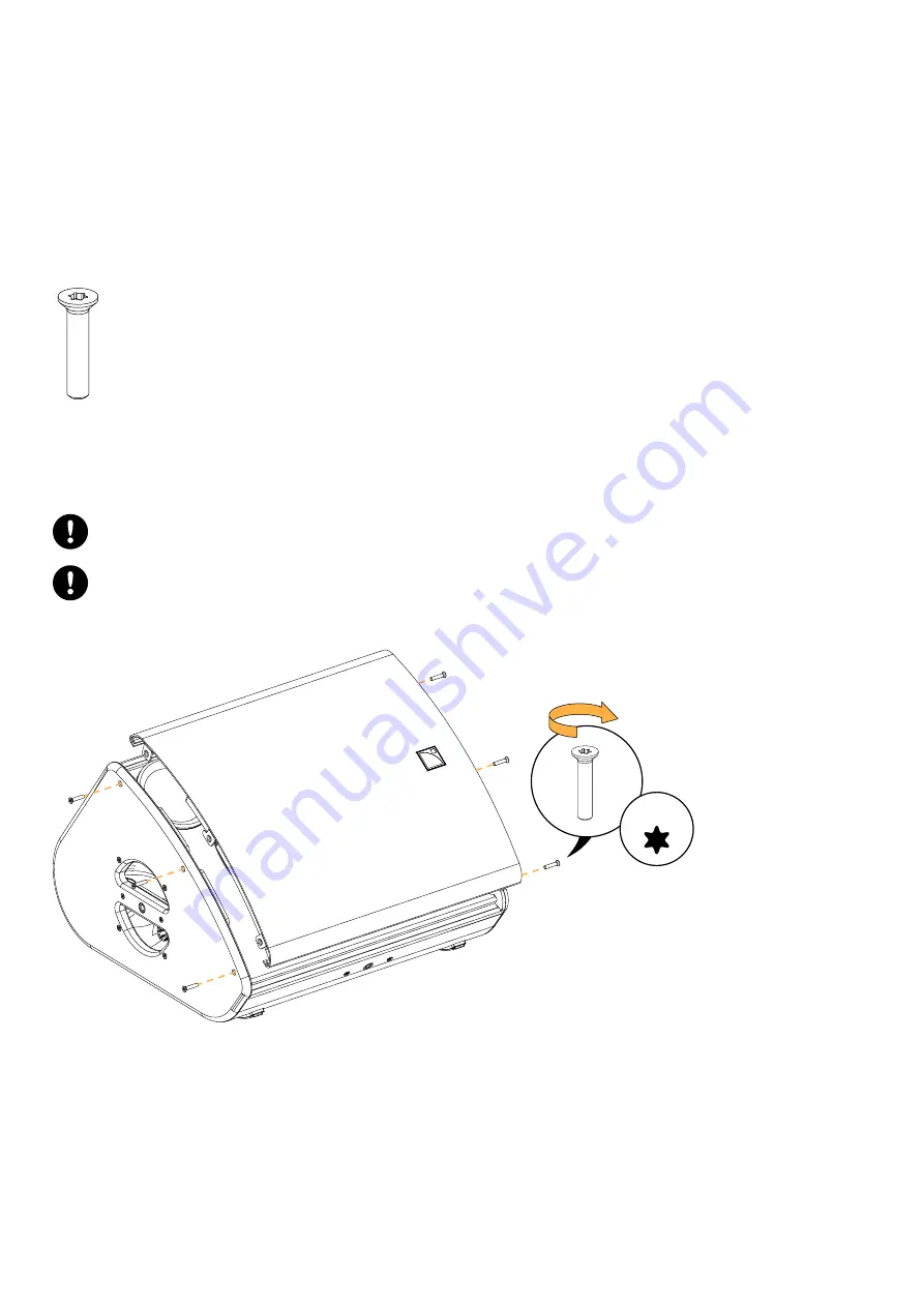
Repair kit
G03169 - KR coaxial speaker X12 or
G03175 - KR diaphragm X12
×6
S100033
M5×25 Torx
Exploded view
For safety reasons, always use the new screws and spare parts provided in the KR.
If no new screws are available, use blue threadlocker.
Gradually tighten the screws following a star pattern.
Position the logo on the right side.
x6
5 N.m
T25
76
X12 owner's manual (EN) version 1.0
Содержание KIVA SB15M
Страница 1: ...X12 owner s manual EN ...
Страница 64: ...Rigging procedures b Finally store the lever on the right 64 X12 owner s manual EN version 1 0 ...
Страница 66: ...Rigging procedures 6 Lift the assembly 66 X12 owner s manual EN version 1 0 ...
Страница 80: ...Forbidden con gurations Forbidden con gurations Forbidden Authorized 80 X12 owner s manual EN version 1 0 ...
Страница 81: ...Forbidden con gurations Forbidden Authorized X12 owner s manual EN version 1 0 81 ...
Страница 100: ...L Acoustics 13 rue Levacher Cintrat 91460 Marcoussis France 33 1 69 63 69 63 info l acoustics com www l acoustics com ...


