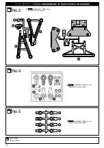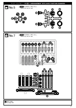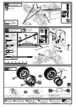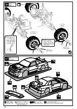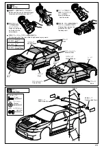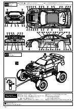
No.1, No.7
19
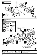
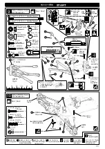
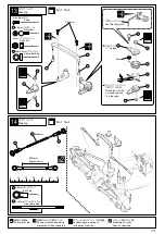
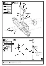
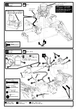
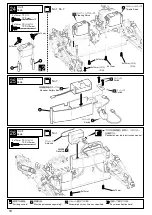
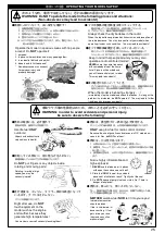
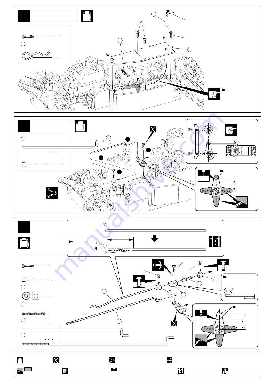
Make sure to place
the cord inside of
the box.
27
Radio
Antenna
1
57
Hook Pin
2x8mm
2x8mm
58
57
56
3
2 x 8mm
TP Screw
No.1,
No.7
No.1, No.7
62
60
63
64
60
61
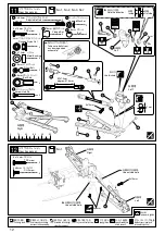
3x3mm
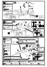
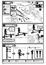
28
Radio
29
Radio
2
60 2mm
Stopper
1
61
Spring
Brake Rod
1
64
Servo Horn
Note the top
and bottom.
2mm
Holes used.
The hole used.
approx.
16mm
approx.10mm
approx.14mm
Supplied with the servo.
2
3 x 3mm
Set Screw
1
3 x 3mm
Set Screw
1
63
Throttle Rod
Bend.
1
59
Steering Rod
90
90
2mm
3
1
2
4
59
3x3mm
2x8mm
3x3mm
20mm
1
2 x 8mm
TP Screw
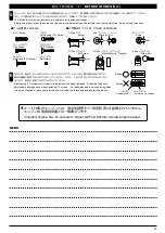
Part bags used.
Assemble in the specified order.
Pay close attention here!
Temporarily tighten.
Ensure smooth non-binding movement while assembling.
Cut off shaded portion.
Drill holes with the specified diameter.
2mm
True-to-scale diagram.
Must be purchased separately!
コードを挟まない
ように注意。
プロポ
フックピン
アンテナ
TP
ビス
プロポ
セットビス
ストッパー
スプリング
ブレーキロッド
約
16mm
約
10mm
使用する穴。
上下の向きに注意。
サーボホーン
スロットルロッド
少し曲げる。
TP
ビス
プロポ
セットビス
約
14mm
使用する穴。
ステアリングロッド
サーボ付属
使用する袋詰。
番号の順に組立てる。
注意して組立てる所。
仮止め。
可動するように組立てる。
をカットする。
2mm
の穴をあける(例)。
原寸図。
別購入品。

