background image

2H9

1-5-16

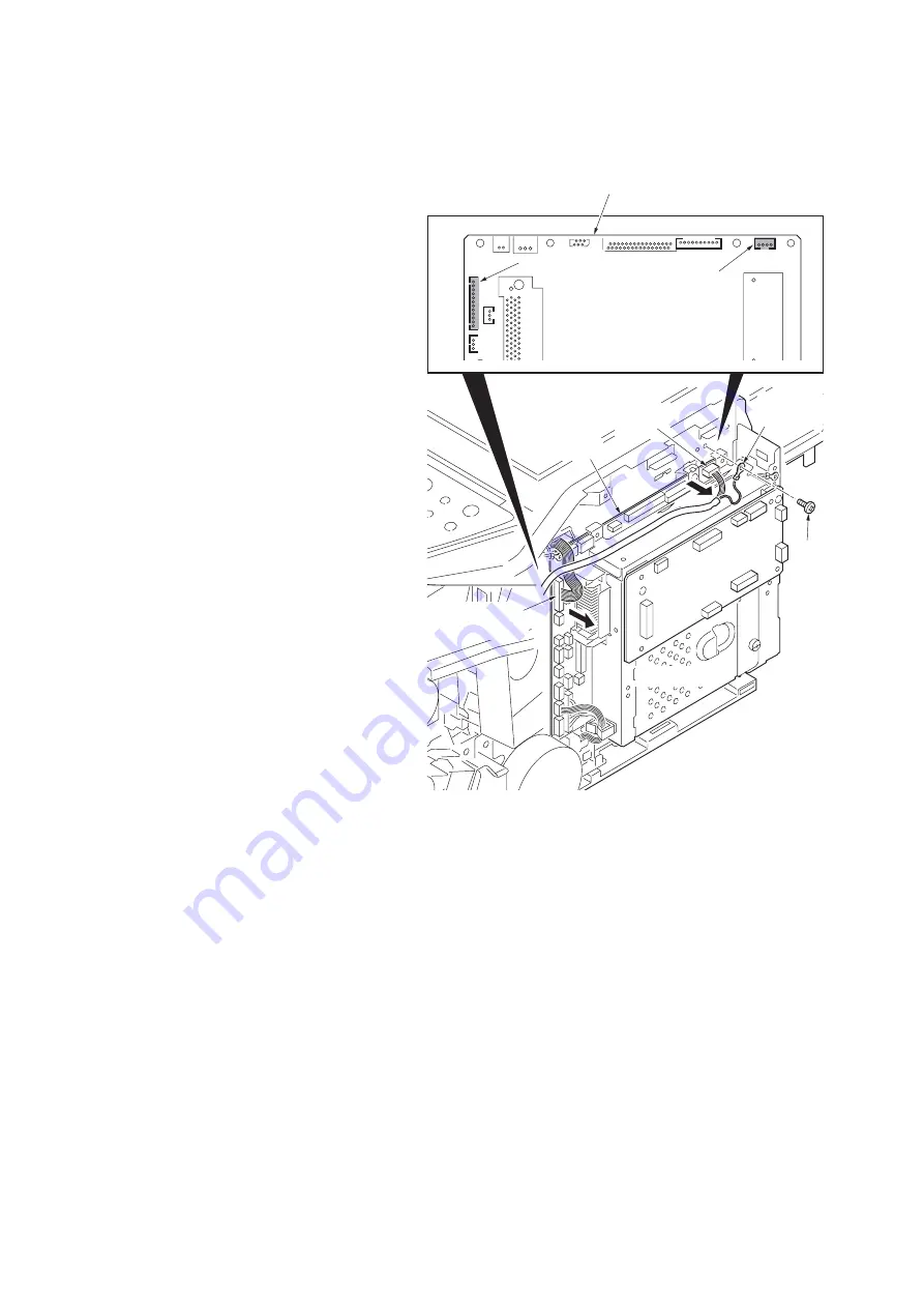
(3) Detaching and refitting the laser scanner unit (LSU)

Procedure

1. Remove the scanner unit (See page 1-5-

13).

2. Remove the screw and then remove the 

grounding terminal.

3. Remove two connectors from the control 

PWB.

Figure 1-5-20

Control PWB

Connector

Connector

YC3

YC10

Screw

Grounding
terminal

Connector
(YC10)

Connector
(YC3)

Control PWB

Содержание KM-2810

Страница 1: ...SERVICE MANUAL Published in May 2009 2H9SM060 First Edition KM 2810 ...

Страница 2: ...icials for details in your area for proper disposal ATTENTION IL Y A UN RISQUE D EXPLOSION SI LA BATTERIE EST REMPLACEE PAR UN MODELE DE TYPE INCORRECT METTRE AU REBUT LES BATTERIES UTILISEES SELON LES INSTRUC TIONS DONNEES Il peut être illégal de jeter les batteries dans des eaux d égout municipales Vérifiez avec les fonc tionnaires municipaux de votre région pour les détails concernant des déche...

Страница 3: ...Revision history Revision Date Replaced pages Remarks ...

Страница 4: ...This page is intentionally left blank ...

Страница 5: ...rsonnel to ensure the safety of their customers their machines as well as themselves during maintenance activities Service personnel are advised to read this booklet carefully to familiarize themselves with the warnings and precautions described here before engaging in maintenance activities ...

Страница 6: ... this symbol CAUTION Bodily injury or damage to property may result from insufficient attention to or incorrect compliance with warning messages using this symbol Symbols The triangle symbol indicates a warning including danger and caution The specific point of attention is shown inside the symbol General warning Warning of risk of electric shock Warning of high temperature indicates a prohibited ...

Страница 7: ... or dusty place This may cause fire or electric shock Do not install the copier near a radiator heater other heat source or near flammable material This may cause fire Allow sufficient space around the copier to allow the ventilation grills to keep the machine as cool as possible Insufficient ventilation may cause heat buildup and poor copying performance Always handle the machine by the correct l...

Страница 8: ... carefully Always check that the copier is correctly connected to an outlet with a ground connection Check that the power cable covering is free of damage Check that the power plug is dust free If it is dirty clean it to remove the risk of fire or electric shock Never attempt to disassemble the optical unit in machines using lasers Leaking laser light may damage eyesight Handle the charger section...

Страница 9: ...r trapped wire and missing screws Check that all the caution labels that should be present on the machine according to the instruction handbook are clean and not peeling Replace with new ones if necessary Handle greases and solvents with care by following the instructions below Use only a small amount of solvent at a time being careful not to spill Wipe spills off completely Ventilate the room wel...

Страница 10: ...This page is intentionally left blank ...

Страница 11: ... the top edge or back of the paper 1 4 14 10 Undulated printing at the right edge scanning start position 1 4 14 1 4 4 Electric problems 1 4 15 1 4 5 Mechanical problems 1 4 18 1 5 Assembly and Disassembly 1 5 1 Precautions for assembly and disassembly 1 5 1 1 Precautions 1 5 1 2 Drum 1 5 1 3 Toner 1 5 1 4 How to tell a genuine Kyocera Mita toner container 1 5 2 1 5 2 Outer covers 1 5 3 1 Detachin...

Страница 12: ...1 1 6 2 Remarks on control PWB replacement 1 6 2 2 1 Mechanical Construction 2 1 1 Paper feed conveying section 2 1 1 1 Cassette paper feed section 2 1 1 2 MP tray paper feed section 2 1 2 3 Paper conveying section 2 1 3 2 1 2 Drum section 2 1 4 1 Drum section 2 1 4 2 Main charger unit 2 1 5 2 1 3 Optical section 2 1 6 1 Scanner unit 2 1 6 2 Image scanner unit ISU 2 1 7 3 Laser scanner unit 2 1 9 ...

Страница 13: ...ette When using the document processor 8 7 0 5 seconds When the document processor is not used 6 9 0 5 seconds Warm up time 22 C 71 6 F 60 RH Power on 20 seconds Recovery from the low power mode 15 seconds or less Recovery from the sleep mode 15 seconds or less Paper capacity Cassette 250 sheets 80 g m2 MP tray 50 sheet 80 g m2 plain paper Letter A4 or smaller Output tray capacity 150 sheets 80 g ...

Страница 14: ...B host 1 port Ethernet 1 port 10BASE T 100BASE TX Page description language PDL PRESCRIBE Scanning functions Compatible operation system Windows 2000 Service Pack 2 or later Windows XP Windows Vista Windows Server 2003 Windows Server 2008 System requirements IBM PC AT compatible CPU Celeron 600 MHz or higher RAM 128 MB or more HDD free space 20 MB or more Interface Ethernet Resolution 600 dpi 400 ...

Страница 15: ...te 4 Operation panel 5 Top cover 6 Front cover 7 Main charger cleaner 8 Drum unit 9 Lock lever 10 Toner container 11 Top tray 12 Paper length guide 13 Paper stopper 14 Paper width guides 15 Cassette 16 Paper width guides MP tray 17 MP Multi Purpose tray 18 MP tray extension 19 USB Interface connector 20 Network Interface connector 21 Rear cover 22 Main power switch 23 Power cord connector ...

Страница 16: ... key 4 Address Book key 5 Address Recall key 6 Confirm Destination key 7 Add Destination key 8 One touch keys 9 Message display 10 Document Box key 11 Send key 12 Left Select key 13 Right Select key 14 Function Menu key 15 Numeric keys 16 Clear key 17 Reset key 18 Power key 19 Back key 20 OK key 21 Arrow key 22 Start key 23 Stop key 24 Program keys 25 Logout key ...

Страница 17: ...path option Light path 1 Cassette 2 MP tray 3 Paper feed conveying section 4 Toner container 5 Developing unit 6 Main charger unit 7 Drum unit 8 Laser scanner unit LSU 9 Transfer separation section 10 Fuser section 11 Exit section 12 Duplex conveying section 13 Scanner section 14 Image scanner unit ISU ...

Страница 18: ...2H9 1 1 6 This page is intentionally left blank ...

Страница 19: ... environmental temperature and cool or hot direct air Avoid places subject to dust and vibrations Choose a surface capable of supporting the weight of the machine Place the machine on a level surface maximum allowance inclination 1 Avoid air borne substances that may adversely affect the machine or degrade the photoconductor such as mer cury acidic of alkaline vapors inorganic gasses NOx SOx gases...

Страница 20: ...2 Outer case 3 Inner frame 4 Bottom pad L 5 Bottom pad R 6 Machine cover 7 Top pad L 8 Top pad R 9 Accessory spacer 10 Toner container 11 Plastic bag 12 Power cord 13 Plastic bag 250 600 14 Operation labels 15 Operation label pad 16 Plastic bag 240 350 17 Operation guide holder 18 Documents etc ...

Страница 21: ...9 1 2 3 1 Removing the tapes Procedure 1 Remove two tapes 1 Open the sheet Figure 1 2 3 2 Open the original cover 3 Remove the sheet 4 Remove the paper Figure 1 2 4 Tapes Sheet Original cover Sheet Paper ...

Страница 22: ...2H9 1 2 4 5 Remove nine tapes Figure 1 2 5 Tape Tapes Tapes Tapes Tapes ...

Страница 23: ...nsert the expansion memory into the mem ory socket so that the notches on the mem ory align with the corresponding protrusions in the slot 6 Close the memory slot cover 7 Secure the screw 8 Refit the right side cover 9 Print a status page to check the memory expansion If memory expansion has been properly per formed information on the installed memory is printed with the total memory capacity has ...

Страница 24: ...2H9 1 2 6 This page is intentionally left blank ...

Страница 25: ...Enter 001 using the cursor up down keys or numeric keys and press the start key Enter the maintenance item number using the cursor up down keys or numeric keys The selected maintenance item is run Press the stop key Press the start key Start End Maintenance mode is entered The maintenance item is selected Maintenance mode is exited Repeat the same maintenance item Run another maintenance item No N...

Страница 26: ...sting the scanner center line 0 0 U068 Adjusting the scanning position for originals from the DP 0 0 U070 Adjusting the DP magnification 0 U071 Adjusting the DP scanning timing 0 0 0 0 0 U072 Adjusting the DP center line 0 0 U073 Checking scanner operation U087 Setting DP reading position modification operation 125 125 120 U089 Outputting a MIP PG pattern U093 Setting the exposure density gradient...

Страница 27: ... for scanning an original from the DP 3 0 2 5 3 0 4 0 U411 Adjusting the scanner automatically U425 Setting the target Others U901 Checking copy counts by paper feed locations U903 Checking clearing the paper jam counts U904 Checking clearing the service call counts U905 Checking clearing counts by optional devices U908 Checking the total counter value U910 Clearing the black ratio data U911 Check...

Страница 28: ...put If not specify the paper feed location When output is complete the screen for selecting an item is displayed U001 Exiting the maintenance mode Description Exits the maintenance mode and returns to the normal copy mode Purpose To exit the maintenance mode Method Press the start key The normal copy mode is entered U002 Setting the factory default data Description Restores the machine conditions ...

Страница 29: ...the part number or to decide if the newest version of ROM is installed Method 1 Press the start key The ROM version are displayed 2 Change the screen using the cursor left right keys Completion Press the stop key The screen for selecting a maintenance item No is displayed Maintenance item No Description Display Description MAIN Control PWB ROM MMI Operation panel PWB ROM ENGINE Engine ROM ENGINE B...

Страница 30: ...e destination setting 4 Turn the main power switch off and on An error code is displayed in case of an initialization error When errors occurred turn main power switch off then on and execute initialization using maintenance item U021 Error codes Maintenance item No Description Codes Description ERROR 01 Configuration initialization error ERROR 02 Counter initialization error ERROR 03 One touch in...

Страница 31: ...ng operate correctly Method 1 Press the start key 2 Turn each switch sensor on and off manually to check the status When a switch sensor is detected to be in the ON position the display for that switch sensor will be 1 Option Completion Press the stop key The screen for selecting a maintenance item No is displayed Maintenance item No Description Display Operation MAIN Main motor operates PAPER FEE...

Страница 32: ...ation of each solenoid Method 1 Press the start key 2 Select the solenoid to be operated 3 Press the start key The solenoid turns on Option 4 To stop operation press the stop key Completion Press the stop key The screen for selecting a maintenance item No is displayed Maintenance item No Description Display Clutches FEED CL Paper feed clutch operates REG CL Registration clutch operates DLP CL Deve...

Страница 33: ... system menu key 5 Change the setting value using the cursor left right keys For output example 1 decrease the value For output example 2 increase the value Figure 1 3 1 6 Press the start key The value is set Caution Check the copy image after the adjustment If the image is still incorrect perform the following adjustments in maintenance mode Maintenance item No Description Display Description LSU...

Страница 34: ...ge after the adjustment If the image is still incorrect perform the following adjustments in maintenance mode Maintenance item No Description Display Description Setting range Initial setting Change in value per step LEFT Adjustment of reference value 0 to 1180 235 1 dot MP TRAY Paper feed from MP tray 70 to 70 0 1 dot CASSETTE 1 Paper feed from cassette 1 70 to 70 0 1 dot CASSETTE 2 Paper feed fr...

Страница 35: ...ase the value For output example 2 decrease the value The greater the value the larger the deflection the smaller the value the smaller the deflection Figure 1 3 3 7 Press the start key The value is set Completion Press the stop key The indication for selecting a maintenance item No appears Maintenance item No Description Display Description Setting range Initial setting Change in value per step D...

Страница 36: ...ion in the auxiliary scanning direction Change the setting value using the cursor left right keys Increasing the setting makes the image longer in the auxiliary scanning direction and decreasing it makes the image shorter in the auxiliary scanning direction 5 Press the start key The value is set Completion Press the stop key The indication for selecting a maintenance item No appears Maintenance it...

Страница 37: ...t key 2 Change the setting using the cursor left right keys Increasing the setting moves the shading position toward the machine left and decreasing it moves the position toward the machine right 3 Press the start key The value is set Supplement While this maintenance item is being executed copying from an original is available in interrupt copying mode which is activated by pressing the system me...

Страница 38: ...5 5 Press the start key The value is set Adjustment Auxiliary scanning direction 1 Press the system menu key 2 Place an original and press the start key to make a test copy 3 Press the system menu key 4 Change the setting value using the cursor left right keys For copy example 1 increase the value For copy example 2 decrease the value Figure 1 3 6 5 Press the start key The value is set Completion ...

Страница 39: ... copy example 1 increase the value For copy example 2 decrease the value Figure 1 3 7 7 Press the start key The value is set Caution Check the copy image after the adjustment If the image is still incorrect perform the following adjustments in maintenance mode Completion Press the stop key The screen for selecting a maintenance item No is displayed Maintenance item No Description Display Descripti...

Страница 40: ...s For copy example 1 decrease the value For copy example 2 increase the value Figure 1 3 8 7 Press the start key The value is set Caution Check the copy image after the adjustment If the image is still incorrect perform the following adjustments in maintenance mode Completion Press the stop key The screen for selecting a maintenance item No is displayed Maintenance item No Description Display Desc...

Страница 41: ...Press the start key The value is set 5 Select BLACK LINE of the screen for selecting an item 6 Select the scanning position using the cursor left right keys 7 Press the start key The value is set 8 Set the original the one which density is known in the DP and press the system menu key The screen for the test copy mode is displayed 9 Press the start key Test copy is executed 10 Perform the test cop...

Страница 42: ...alue using the or cursor left right keys For copy example 1 increase the value For copy example 2 decrease the value Figure 1 3 9 5 Press the start key The value is set Caution Check the copy image after the adjustment If the image is still incorrect perform the following adjustments in maintenance mode Completion Press the stop key The screen for selecting a maintenance item No is displayed Maint...

Страница 43: ...mple 1 increase the value For copy example 2 decrease the value Figure 1 3 10 5 Press the start key The value is set Caution Check the copy image after the adjustment If the image is still incorrect perform the following adjustments in maintenance mode Maintenance item No Description Display Description Setting range Initial setting Change in value per step FRONT HEAD Leading edge registration fir...

Страница 44: ... For copy example 1 increase the value For copy example 2 decrease the value Figure 1 3 11 5 Press the start key The value is set Caution Check the copy image after the adjustment If the image is still incorrect perform the following adjustments in maintenance mode Completion Press the stop key The screen for selecting a maintenance item No is displayed Maintenance item No Description Original Cop...

Страница 45: ... using the cursor left right keys For copy example 1 increase the value For copy example 2 decrease the value Figure 1 3 12 7 Press the start key The value is set Caution Check the copy image after the adjustment If the image is still incorrect perform the following adjustments in maintenance mode Completion Press the stop key The screen for selecting a maintenance item No is displayed Maintenance...

Страница 46: ...ct DUST CHECK 2 Press the start key The exposure lamp lights 3 To turn the exposure lamp off press the stop key Method DP READING 1 Select DP READING 2 Press the start key The mirror frame of the scanner moves to the reading position Completion Press the stop key when scanning stops The screen for selecting a maintenance item No is displayed Maintenance item No Description Display Description SCAN...

Страница 47: ...elected item is displayed Setting Standard data when dust is detected 1 Select the item to be set 2 Change the value using the cursor left right keys 3 Press the start key The value is set Setting Initialization of original reading position 1 Select CLEAR 2 Press the start key The setting is cleared Completion Press the stop key The screen for selecting a maintenance item No is displayed Maintenan...

Страница 48: ...egister the setting 4 Press the system menu key 5 Press the start key A MIP PG pattern is output 6 To return to the screen for selecting an item press the system menu key Completion Press the stop key The screen for selecting a maintenance item No is displayed Maintenance item No Description Display PG pattern to be output Purpose Gray Scale To check the laser scanner unit engine output characteri...

Страница 49: ...Figure 1 3 13 3 Press the start key The value is set 4 To return to the screen for selecting an item press the stop key Supplement While this maintenance item is being executed copying from an original is available in interrupt copying mode which is activated by pressing the system menu key Completion Press the stop key The screen for selecting a maintenance item No is displayed Maintenance item N...

Страница 50: ...etting 1 Press the start key 2 Change the setting value using the cursor left right keys 3 Press the start key The value is set Completion Press the stop key The screen for selecting a maintenance item No is displayed U111 Checking the drum drive time Description Displays the drum drive time for checking a figure which is used as a reference when correcting the high volt age based on time Purpose ...

Страница 51: ...l setting for the developing unit Description Replenishes toner to the developing unit to a certain level from the toner container that has been installed Purpose To operate when installing the machine or replacing the developing unit Method 1 Press the start key 2 Select ON 3 Press the start key Toner installation is started and the output value of the sensor and execution time are displayed Comp...

Страница 52: ...tenance item No is displayed U157 Checking the developing drive time Description Displays the developing drive time for checking Purpose To check the developing drive time after replacing the developing unit Method 1 Press the start key The developing drive time is displayed in minutes Completion Press the stop key The screen for selecting a maintenance item No is displayed Maintenance item No Des...

Страница 53: ...enance item No is displayed U200 Turning all LEDs on Description Turns all the LEDs on the operation panel on Purpose To check if all the LEDs on the operation panel light Method 1 Press the start key 2 Select EXECUTE and press the start key All the LEDs on the operation panel light 3 Press the stop key The LEDs turns off Completion Press the stop key The screen for selecting a maintenance item No...

Страница 54: ...ayed and the leftmost LED on the operation panel lights 3 As the keys lined up in the same line as the lit indicator are pressed in the order from the top to the bot tom the figure shown on the touch panel increases in increments of 1 When all the keys in that line are pressed and if there are any LEDs corresponding to the keys in the line on the immediate right the top LED in that line will light...

Страница 55: ...or solenoids and clutch Method 1 Press the start key 2 Select the item to be operated 3 Press the start key The operation starts 4 To stop operation press the stop key Completion Press the stop key when operation stops The screen for selecting a maintenance item No is displayed Maintenance item No Description Display Description UNLOCK Release the lock of the operation from the system menu PARTIAL...

Страница 56: ...e numeric keys 2 Press the start key The value is set Clearing 1 Select CLEAR 2 Press the start key The count is cleared Completion Press the stop key The screen for selecting a maintenance item No is displayed U251 Checking clearing the maintenance count Description Displays clears and changes the maintenance count Purpose To check the maintenance count Also to clear the count during maintenance ...

Страница 57: ...s U253 Switching between double and single counts Description Switches the count system for the total counter and other counters Purpose Used to select according to the preference of the user copy service provider if A4 Letter paper is to be counted as one sheet single count or two sheets double count Setting 1 Press the start key 2 Select the count system Initial setting DBL COUNT FOLIO 3 Press t...

Страница 58: ... setting is set Completion Press the stop key The screen for selecting a maintenance item No is displayed U265 Setting OEM purchaser code Description Sets the OEM purchaser code Purpose Sets the code when replacing the main PWB and the like Setting 1 Press the start key 2 Change the preset value using the cursor left right keys 3 Press the start key The setting is set Completion Press the stop key...

Страница 59: ...ser request sets or cancels restriction on the number of sheets Setting 1 Press the start key 2 Select ON or OFF Initial setting ON 3 Press the start key The setting is set Completion Press the stop key The screen for selecting a maintenance item No is displayed U343 Switching between duplex simplex copy mode Description Switches the initial setting between duplex and simplex copy Purpose To be se...

Страница 60: ...of the maintenance count reaches the set value the message is displayed Purpose To change the time for maintenance due indication Setting 1 Press the start key 2 Change the setting using the cursor left right keys 3 Press the start key The value is set Completion Press the stop key The screen for selecting a maintenance item No is displayed Maintenance item No Description Display Description Setti...

Страница 61: ...et Caution Check the copy image after the adjustment If the image is still incorrect perform the following adjustments in maintenance mode Completion Press the stop key The screen for selecting a maintenance item No is displayed Maintenance item No Description Display Description Setting range Initial setting Change in value per step LEAD Printer leading edge margin 0 to 100 30 0 1 mm A Margin Pri...

Страница 62: ... 7 Press the start key The value is set Caution Check the copy image after the adjustment If the image is still incorrect perform the following adjustments in maintenance mode Completion Press the stop key The indication for selecting a maintenance item No appears Maintenance item No Description Display Description Setting range Initial setting Change in value per step A Margin Scanner left margin...

Страница 63: ... key 6 Change the setting value using the cursor left right keys Increasing the value makes the margin wider and decreasing it makes the margin narrower Figure 1 3 16 7 Press the start key The value is set Completion Press the stop key The screen for selecting a maintenance item No is displayed Maintenance item No Description U403 P 1 3 38 U402 P 1 3 37 U404 Display Description Setting range Initi...

Страница 64: ...een for selecting an item press the stop key Method DP 1 Select ADJUST DP 2 Set a specified original P N 302AC68243 in the DP Cut the trailing edge of the original Figure 1 3 17 3 Press the start key Auto adjustment starts When automatic adjustment has normally completed OK is displayed If a problem occurs during auto adjustment NG XX XX is replaced by an error code is displayed and operation stop...

Страница 65: ...b of the original at D 30 mm from the left edge E 148 5 mm from the left edge and F 267 mm from the left edge respectively 2 Apply the following formula for the values obtained D F 2 E 2 5 Enter the values solved using the cursor left right keys in SUB LEAD 6 Press the start key The value is set 7 Measure the length G from the leading edge of the black belt b to the bottom of the N475 patch of the...

Страница 66: ... When an optional paper feed device is not installed the corresponding count is not displayed Completion Press the stop key The screen for selecting a maintenance item No is displayed Maintenance item No Description 30 mm A D F B C 35 mm Leading edge Left edge Black belt a Black belt b 110 mm 185 mm 148 5 mm 267 mm Original for adjustment P N 302FZ56990 E G MAIN ADJ A C 2 B 2 SUB LEAD ADJ D F 2 E ...

Страница 67: ...ys or clears the service call code counts by types Purpose To check the service call code status by types Also to clear the service call code counts after replacing con sumable parts Method 1 Press the start key 2 Select the item The screen for executing is displayed Method Displays clears the service call counts 1 Select COUNT The count for service call detection by type is displayed 2 Change the...

Страница 68: ...lears the accumulated black ratio data for A4 sheet Purpose To clear data as required at times such as during maintenance service Method 1 Press the start key 2 Select ALL CLEAR 3 Press the start key The accumulated black ratio data is cleared Completion Press the stop key The screen for selecting a maintenance item No is displayed U911 Checking clearing copy counts by paper sizes Description Disp...

Страница 69: ...onds before pressing the Start key to allow the machine to recognize the USB memory 9 Press the start key Starts reading or writing The progress of selected item is displayed in When an error occurs the operation is canceled and an error code is displayed 10 When normally completed FIN is displayed 11 Turn the main power switch off and on after completing writing when selecting IMPORT Completion P...

Страница 70: ...e life counts is displayed Completion Press the stop key The screen for selecting a maintenance item No is displayed U942 Setting of deflection for feeding from DP Description Adjusts the deflection generated when the optional DP is used Purpose Use this mode if an original non feed jam oblique feed or wrinkling of original occurs when the DP is used Setting 1 Press the start key 2 Select the item...

Страница 71: ... Once the print data is stored into USB memory OK will be displayed Completion Press the stop key The screen for selecting a maintenance item No is displayed U991 Checking the scanner count Description Displays the scanner operation count Purpose To check the status of use of the scanner Method 1 Press the start key Completion Press the stop key The screen for selecting a maintenance No item is di...

Страница 72: ...tart key 2 Select the VTC PG pattern to be output 3 Press the system menu key 4 Press the start key A VTC PG pattern is output 5 To return to the screen for selecting an item press the system menu key Completion Press the stop key The screen for selecting a maintenance item No is displayed Maintenance item No Description Display PG pattern to be output Purpose PG1 Leading edge registration adjust ...

Страница 73: ...l To remove paper misfed in the printer pull out the paper cassette open the front cover rear cover or duplexer s cover or remove the drum unit Figure 1 4 1Paper misfeed indication 2 Paper misfeed detection condition Figure 1 4 2 Help Paper jammed in the printer JAM Peper feeder 1 Option Peper feeder 2 Option Printer Registration sensor Paper sensor MP paper sensor Exit sensor PF paper feed sensor...

Страница 74: ...etected the printer stops printing and display an error message on the operation panel An error message consists of a message prompting a contact to service personnel total print count and a four digit error code indicating the type of the error The display varies depending on the type of the error Figure 1 4 3 Machine failure Call service C ...

Страница 75: ...See page 1 5 35 0170 Billing counting error Defective control PWB Replace the control PWB See page 1 5 35 0420 Paper feeder communication error Communication error between control PWB and optional paper feeder Improper installa tion paper feeder Follow installation instruction carefully again Defective harness between control PWB YC30 and paper feeder inter face connector or improper connec tor in...

Страница 76: ...e remedy or replace the harness Refer to the service manual for the paper feeder Defective PF paper feed motor drive transmission system Check if the gears rotate smoothly If not grease the bushings and gears Check for broken gears and replace if any Defective PF main motor Replace the PF main motor Defective control PWB Replace the control PWB See page 1 5 35 2620 PF paper feed motor error Option...

Страница 77: ...FFC insertion Reinsert the FFC Also check for continuity within the FFC If none remedy or replace the FFC Defective home position sensor Replace the home position sensor Defective harness between ISU motor and scanner PWB YC104 or improper connec tor insertion Reinsert the connector Also check for conti nuity within the connector harness If none remedy or replace the harness Defective ISU motor Re...

Страница 78: ...between inverter PWB YC102 and exposure lamp or improper connec tor insertion Reinsert the connector Also check for conti nuity within the connector harness If none remedy or replace the harness Defectiveexposure lamp Replace the exposure lamp See page 1 5 23 Defective inverter PWB Replace the inverter PWB See page 1 5 23 Defective control PWB Replace the control PWB See page 1 5 35 3300 AGC error...

Страница 79: ...wer off for at least 30 min utes then turn printer on again If not cured replace the laser scanner unit See page 1 5 16 Defective laser scanner unit Replace the laser scanner unit See page 1 5 16 Defective control PWB Replace the control PWB See page 1 5 35 6000 Broken fuser heater lamp wire The fuser temperature does not rise after the fuser heater lamp has been turned on Poor contact in the fuse...

Страница 80: ...ective connec tion between power source PWB YC103 and high voltage PWB YC201 Reinsert the connector Defective power source PWB Replace the power source PWB See page 1 5 38 Defective control PWB Replace the control PWB See page 1 5 35 7990 Waste toner full The waste toner sensor has detected that the waste toner reservoir drum unit is full Waste toner reser voir drum unit is full Turn the main powe...

Страница 81: ...trol PWB Turn the main power switch off on to restart the printer If the error is not resolved replace control PWB See page 1 5 35 F050 Control PWB engine checksum error Some error may have occurred when downloading the firmware of the control PWB Download the firmware of the control PWB again using the memory card Defective control PWB Turn the main power switch off on to restart the printer If t...

Страница 82: ...e page 1 4 12 See page 1 4 12 See page 1 4 12 6 Black vertical streaks 7 Unsharpness 8 Gray background 9 Dirt on the top edge or back of the paper 10 Undulated print ing at the right edge scanning start posi tion See page 1 4 13 See page 1 4 13 See page 1 4 13 See page 1 4 14 See page 1 4 14 ABC 123 ABC 123 ABC 123 ABC 123 ABC 123 ABC 123 This vertical line should be straight ...

Страница 83: ...voltage PWB Poor contact of transfer bias terminal spring and transfer bias terminal T J201 J202 J203 on the high volt age PWB Check the high voltage PWB visually and correct or replace if necessary See page 1 5 41 Defective laser scanner unit Replace the laser scanner unit See page 1 5 16 Defective control PWB Replace the control PWB See page 1 5 35 Print example Causes Check procedures correctiv...

Страница 84: ...e one that satisfies the paper specifica tions Defective transfer roller installation The transfer roller must be supported by the bushes at the both ends Clean the bush to remove oil and debris Replace the transfer roller if necessary See page 1 5 28 Defective transfer bias output Replace the high voltage PWB or control PWB See page 1 5 41 or 1 5 35 Print example Causes Check procedures correctiv...

Страница 85: ...the both ends Clean the bush to remove oil and debris Replace the transfer roller if necessary See page 1 5 28 Defective transfer bias output Replace the high voltage PWB or control PWB See page 1 5 41 or 1 5 35 EcoPrint mode setting The EcoPrint mode can provides faint unsharp printing because it acts to conserve toner for draft printing purpose For normal printing turn the EcoPrint mode off by u...

Страница 86: ...the drum and developing unit and the fuser unit inlet Clean these areas and parts to remove toner Defective transfer roller If the transfer roller is contaminated with toner clean the trans fer roller using a vacuum cleaner or by continuously printing a low density page until the symptom has faded away Print example Causes Check procedures corrective measures Defective polygon motor laser scan ner...

Страница 87: ... Also check for continuity within the con nector harness If none remedy or replace the harness Defective control PWB Replace the control PWB See page 1 5 35 3 Left cooling fan motor does not oper ate Broken left cooling fan motor coil Check for continuity across the coil If none replace the left cool ing fan motor Defective harness between left cooling fan motor and control PWB YC104 or improper c...

Страница 88: ... the connector Also check for continuity within the con nector harness If none remedy or replace the harness Defective control PWB Replace the control PWB See page 1 5 35 9 Duplex solenoid does not operate Broken duplex solenoid coil Check for continuity across the coil If none replace the duplex solenoid Defective harness between duplex solenoid and control PWB YC29 or improper connector insertio...

Страница 89: ...e registration sen sor on the high voltage PWB Replace the high voltage PWB See page 1 5 41 Defective exit sensor Replace the exit sensor 13 Attention indica tor is lit when the front cover is closed Defective interlock switch on the power source PWB Check for continuity across the interlock switch If there is no con tinuity when the interlock switch is on replace the power source PWB See page 1 5...

Страница 90: ... at one time Check if the separator pad or MPF separation pad is worn Replace the separator pad if it is worn Check if the paper is curled Replace the paper 5 Paper jams Check if the paper is excessively curled Replace the paper Check if the contact between the upper and lower registration rollers is correct Check visually and remedy if necessary Check if the heat roller or press roller is extreme...

Страница 91: ...emoving the hook of the connector be sure to release the hook Take care not to get the cables caught To reassemble the parts use the original screws If the types and the sizes of screws are not known refer to the PARTS LIST 2 Drum Note the following when handling or storing the drum When removing the drum unit never expose the drum surface to strong direct light Keep the drum at an ambient tempera...

Страница 92: ...A black colored band when seen through the left side window A shiny or gold colored band when seen through the right side window The above will reveal that the toner container is a genuine Kyocera Mita branded toner container otherwise it is a coun terfeit Figure 1 5 1 The brand protection seal has an incision as shown below to prohibit reuse Figure 1 5 2 Validation viewer Validation viewer Brand ...

Страница 93: ...ew 2 Unhook four hooks and then remove the rear upper cover Figure 1 5 3 3 Remove the cassette See page 1 5 6 4 Open the front cover 5 Open the rear cover 6 Unhook the hook and then remove the con troller box cover Figure 1 5 4 Screw Hook Hook Hook Hook Rear upper cover Rear upper cover Controller box cover Hook ...

Страница 94: ...2H9 1 5 4 7 Unhook seven hooks and then remove the right cover Figure 1 5 5 Right cover Right cover Right cover Hook Hook Hook Hook Hook Hook Hook ...

Страница 95: ...2H9 1 5 5 8 Unhook six hooks and then remove the left cover Figure 1 5 6 Left cover Left cover Left cover Hook Hook Hook Hook Hook Hook ...

Страница 96: ...e paper feed assembly paper feed roller and pickup roller Procedure 1 Remove the cassette Figure 1 5 7 2 Slide the feed shaft 3 While pressing the lever and then remove the paper feed roller assembly Figure 1 5 8 Cassette Lever Feed shaft Paper feed roller assembly ...

Страница 97: ...t all the removed parts When refitting the paper feed roller assem bly be sure to align the paper feed roller pivot with the slotted hole on the feed shaft Figure 1 5 9 Paper feed roller assembly Paper feed roller assembly Feed shaft Feed shaft Pivot Slotted hole ...

Страница 98: ...e cassette See page 1 5 6 2 Push the bottom plate down until it locks 3 Unhook two hooks and then remove the retard guide Figure 1 5 10 4 Remove the retard roller assembly Figure 1 5 11 Retard guide Retard guide Cassestte Cassette Hook Hook Hook Hook Bottom plate Retard roller Assembly ...

Страница 99: ...etard roller assembly and refit all the removed parts Caution Before refitting the retard roller assembly firmly install the spring onto the projection of the retard roller assembly Figure 1 5 12 Spring Retard roller assembly Projection ...

Страница 100: ... MP paper feed roller Procedure 1 Open the front cover 2 Pull the MP feed holder lever down 3 Slide the MP feed holder 4 Remove the MP paper feed roller Figure 1 5 13 MP feed holder Lever Front cover MP paper feed roller MP paper feed roller ...

Страница 101: ...P paper feed roller be sure to align the paper feed roller pivot with the slotted hole on the MPF feed shaft When refitting the MP paper feed roller be sure to align the MPF feed shaft pivot with the slotted hole on the MP paper feed roller Figure 1 5 14 MPF feed shaft Pivot MP paper feed roller Slotted hole ...

Страница 102: ...2H9 1 5 12 1 5 4 Optical section 1 Detaching and refitting the original holder Procedure 1 Pull the original holder out Figure 1 5 15 Original cover ...

Страница 103: ... page 1 5 12 2 Remove the left cover and right cover See page 1 5 3 3 Remove the FFC and connector from the control PWB 4 Remove three connectors from the scanner PWB Figure 1 5 16 Connector FFC Scanner PWB Scanner PWB Connector Connector Connector YC8 YC7 YC108 YC104 YC105 Control PWB Control PWB ...

Страница 104: ...2H9 1 5 14 5 Release three clamps and then remove the wires Figure 1 5 17 6 Remove two screws Figure 1 5 18 Wires Wires Clamp Clamp Clamp Screw Screw Screw Screw Screw ...

Страница 105: ...2H9 1 5 15 7 Unhook four hooks and then remove the scanner unit Figure 1 5 19 Scanner unit Hooks Hooks ...

Страница 106: ...dure 1 Remove the scanner unit See page 1 5 13 2 Remove the screw and then remove the grounding terminal 3 Remove two connectors from the control PWB Figure 1 5 20 Control PWB Connector Connector YC3 YC10 Screw Grounding terminal Connector YC10 Connector YC3 Control PWB ...

Страница 107: ... from the power source PWB Figure 1 5 21 6 Unhook four hooks and then remove the frame left duct 7 Remove the wires from the clamp Figure 1 5 22 Clamp Clamps Connector Power source PWB Power source PWB YC106 Frame left duct Frame left duct Hook Hook Clamp Wires Hook Hook ...

Страница 108: ...topper and then remove the top cover rack L from the top cover Figure 1 5 23 9 Remove four screws from the top cover Figure 1 5 24 Top cover rack L Stopper Top cover Top cover Top cover rack L Top cover Screw Screw Screw Screw ...

Страница 109: ...re 1 5 25 12 Release the clamp and then pull out the wires 13 Remove four screws and then remove the laser scanner unit LSU 14 Check or replace the laser scanner unit LSU and refit all the removed parts Figure 1 5 26 Top cover Connector Hook Hook Laser scanner unit Wires Clamp Screws Screws ...

Страница 110: ...ure 1 Remove the original holder See page 1 5 12 2 Unhook two hooks by using flat screwdriver from the pits and then detach the operation unit 3 Remove the connector and then remove the operation unit Figure 1 5 27 Hook Pit Pit Hook Connector Operation unit Operation unit ...

Страница 111: ...ove the original holder cover Figure 1 5 28 6 Move the image scanner unit ISU unit to the center 7 Detach the ISU shaft from the holder by lift ing it 8 Remove the FFC Figure 1 5 29 Original holder cover Screw Screw Hooks FFC ISU shaft Holder Image scanner unit ISU ...

Страница 112: ...0 Remove the ISU belt from the hooks of the ISU 11 Pull the ISU shaft out from the ISU unit 12 Check or replace the image scanner unit ISU and refit all the removed parts Figure 1 5 30 Image scanner unit ISU ISU shaft ISU belt Hook Hook ...

Страница 113: ...re 1 Remove the original holder See page 1 5 12 2 Move the image scanner unit ISU unit to the center 3 Unhook five hooks and then remove the lamp mount 4 Remove the connector Figure 1 5 31 Hook Hook Hook Hook Hook Lamp mount Connector Image scanner unit ISU Image scanner unit ISU ...

Страница 114: ...d 250 V ac 0 75 A non time delay when F1 fuse is replaced Figure 1 5 32 8 Unhook three hooks and then remove the ISU reflector Figure 1 5 33 9 Remove the exposure lamp from the hold ers 10 Check or replace the exposure lamp and refit all the removed parts Figure 1 5 34 Inverter PWB Inverter PWB Screw Connector CN2 CN1 F1 ISU reflector Hook Hook Hook Holder Holder Exposure lamp Lamp mount ...

Страница 115: ... section 1 Detaching and refitting the developing unit Procedure 1 Open the front cover 2 Remove the developing unit 3 Check or replace the developing unit and refit all the removed parts Figure 1 5 35 Developing unit Front cover ...

Страница 116: ...Drum section 1 Detaching and refitting the drum unit Procedure 1 Remove the developing unit See page 1 5 25 2 Remove the drum unit 3 Check or replace the drum unit and refit all the removed parts Figure 1 5 36 Drum unit ...

Страница 117: ...rum unit See page 1 5 26 3 Remove the tape 4 While pushing on the main plate slide the main charger unit Figure 1 5 37 5 Remove the main charger unit by lifting it 6 Check or replace the main charger unit and refit all the removed parts Figure 1 5 38 Main charger unit Main charger unit Tape Main plate Drum unit Main charger unit ...

Страница 118: ...ing the transfer roller Procedure 1 Remove the developing unit See page 1 5 25 2 Remove the drum unit See page 1 5 26 3 Slide the paper chute guide and unhook the hooks 4 Remove the paper chute guide Figure 1 5 39 Paper chute guide Paper chute guide Hook Hook Hook Hook ...

Страница 119: ... and refit all the removed parts Caution When refitting the transfer roller be careful about following point Push the release lever to raise the lever end then insert the front of gear Z16 under the release lever end Figure 1 5 41 Transfer roller Shaft Shaft Transfer roller Transfer bush Transfer bush Gear Z16 Release lever Gear Z16 Transfer bush Transfer bush Transfer roller ...

Страница 120: ... 5 3 2 Remove the wires from three clamps 3 Remove the connector from the power source PWB Figure 1 5 42 4 Unhook four hooks and then remove the frame left duct 5 Remove the wires from the clamp Figure 1 5 43 YC105 Clamp Clamps Connctor Power source PWB Power source PWB Frame left duct Frame left duct Hook Clamp Wires Hook Hook Hook ...

Страница 121: ...2H9 1 5 31 6 Remove the connector from the power source PWB Figure 1 5 44 7 Remove the connector from the control PWB Figure 1 5 45 YC102 Connector Connector Power source PWB Connector Control PWB ...

Страница 122: ...2H9 1 5 32 8 Remove the rear cover Figure 1 5 46 9 Remove two screws and then remove the fuser unit Figure 1 5 47 Rear cover Fuser unit Screw Screw ...

Страница 123: ...k or replace the fuser unit and refit all the removed parts Caution When reinstalling the fuser unit tighten up a screw while pressing the fuser unit in order of 1 to 2 Figure 1 5 48 1 2 Fuser unit Screw Screw Fuser unit ...

Страница 124: ...easing the fuser pressure could cause loose toner fusing Procedure 1 Remove the cassette See page 1 5 6 2 Open the duplex cover 3 Slide the fuser lever R and L Normal Flush with the front of the machine Fuser pressure decreased Flush with the rear of the machine Figure 1 5 49 Fuser lever R Duplex cover Fuser lever L R Fuser lever L R Fuser lever L Normal Fuser pressure decreased ...

Страница 125: ...can ner PWB 3 Remove twenty one connectors and two FFCs form the control PWB 4 Remove the wires from the clamp Figure 1 5 50 Scanner PWB Wires Clamp YC29 YC28 YC6 YC8 YC7 FFC FFC YC3 YC19 YC30 YC23 YC25 YC17 YC13 YC16 YC20 YC27 YC21 YC18 YC24 YC10 YC26 YC9 YC12 YC101 YC109 YC108 YC104 YC105 Connectors FFCs Connectors Control PWB Scanner PWB Control PWB ...

Страница 126: ...ing ter minal Figure 1 5 51 6 Unhook the hook and then remove the con trol PWB assembly Figure 1 5 52 Control PWB assembly Screw Screw Screw Screw Screws Grouniding terminal Screw Grouniding terminal Control PWB assembly Control PWB assembly Hook ...

Страница 127: ... or replace the control PWB and refit all the removed parts To replace the control PWB remove the EEPROM U17 from the old control PWB and mount it to the new control PWB Figure 1 5 53 Controller box Screw EEPROM U17 Screw Screw Control PWB Control PWB Screw Screw CF guide ...

Страница 128: ... clamps 3 Remove five connectors from the power source PWB Figure 1 5 54 4 Unhook four hooks and then remove the frame left duct 5 Remove the wire from the clamp Figure 1 5 55 YC107 YC104 YC106 YC108 YC105 Clamp Clamps Connectors Power source PWB Connectors Power source PWB Frame left duct Frame left duct Hook Hook Hook Clamp Wires Hook ...

Страница 129: ... 56 7 Remove five screws 8 Remove three connectors and then remove the power source PWB assembly Figure 1 5 57 Inlet mount Screw YC103 YC102 YC101 Power source PWB Power source PWB assembly Connector Connector Connector Screw Screw Screw Screws Connector Connector Connector ...

Страница 130: ... the power source PWB plate 10 Check or replace the power source PWB and refit all the removed parts Caution The power source PWB sheet must be installed in the specified position Figure 1 5 58 Screws Screw Power source PWB Power source PWB plate Power source PWB sheet Screw ...

Страница 131: ...6 3 Remove the cassette See page 1 5 6 4 Remove the left cover and right cover See page 1 5 3 5 Remove the power source PWB See page 1 5 38 6 Turn the printer with the front side up 7 Remove the stopper 8 Remove the DU holder Figure 1 5 59 9 Pull the DU bush out 10 Remove the DU cover assembly Figure 1 5 60 DU holder Stopper DU bush DU cover assembly ...

Страница 132: ...2H9 1 5 42 11 Remove four screws 12 Unhook three hooks and then remove the lower base cover Figure 1 5 61 Screws Screws Hook Hook Hook Lower base cover ...

Страница 133: ...te pin Figure 1 5 62 15 Remove two connectors and then remove the high voltage PWB 16 Remove the cassette pin holder from the high voltage PWB Figure 1 5 63 Spring Cassette pin Cassette pin Cassette pin holder High voltage PWB High voltage PWB Connectors ...

Страница 134: ...is atop the high voltage PWB Each interface is firmly in contact with each spring The bias contact pin must be installed in the specified position The cassette pin must be inserted in the cassette pin holder Figure 1 5 64 Cassette pin Cassette pin holder High voltage PWB High voltage PWB High voltage PWB Grounding plate Bias contact pin Spring Main charger Spring Developing Spring Transfer ...

Страница 135: ...move six connectors and the FFC from the scanner PWB Figure 1 5 65 3 Remove four screws and then remove the scanner PWB 4 Check or replace the scanner PWB and refit all the removed parts Figure 1 5 66 YC102 YC103 FFCs Connectors Scanner PWB Scanner PWB YC101 YC109 YC108 YC104 YC105 Scanner PWB Screws Screws ...

Страница 136: ...motor Procedure 1 Remove the right cover See page 1 5 3 2 Remove the connector 3 Remove the M3 screw and two M4 screws 4 Remove the main motor 5 Check or replace the main motor and refit all the removed parts Figure 1 5 67 Main motor Connector M3 screw M4 scrws ...

Страница 137: ... motor right cooling fan motor and power source fan motor When detaching or refitting a fan motor be careful of the airflow direction intake or exhaust Figure 1 5 68 Left cooling fan motor Power source fan motor Right cooling fan motor Exhaust Exhaust Intake ...

Страница 138: ...2H9 1 5 48 This page is intentionally left blank ...

Страница 139: ...t has the firmware in the USB port 3 Turn ON the main power switch 4 About 40 seconds later Firmware Update Downloading will be displayed and blinking the memory LED this shows to start the download 5 Display the software that now upgrading 5 minutes Firmware Update Main Engine Scanner 6 Display the completion of the upgrade Memory LED is ON condition Firmware Update Main Completed Engine Complete...

Страница 140: ...Remarks on control PWB replacement When replacing the control PWB remove the EEPROM U17 from the control PWB that has been removed and then reattach it to the new control PWB Figure 1 6 2 EEPROM U17 Control PWB EEPROM ...

Страница 141: ...r to the transfer separation section 1 Cassette paper feed section Figure 2 1 1 Cassette paper feed section Figure 2 1 2Cassette paper feed section block diagram 1 9 7 3 4 5 2 6 8 10 11 1 Pickup roller 2 Paper feed roller 3 Feed holder 4 Retard roller 5 Retard holder 6 Retard guide 7 Bottom plate 8 Bottom pad 9 Cassette base 10 Paper sensor 11 Actuator paper sensor FEDDRN MMOTRDYN YC18 3 Paper sen...

Страница 142: ... paper feed roller 2 MPF separation pad 3 MPF separator 4 MPF bottom plate 5 MPF friction pad 6 MP paper sensor 7 Actuator MP paper sensor 8 MPF frame 9 MPF guide R L 10 MPF base 11 MPF middle tray 12 MPF upper tray 13 MPF turn guide MMOTRDYN YC16 3 MPFDRN MP paper sensor MP paper feed solenoid Main motor Control PWB HANDSN YC21 2 MOTCLK REMOTEN YC17 3 YC17 4 YC17 5 ...

Страница 143: ...ection block diagram 1 4 3 5 2 1 Lower registration roller 2 Upper registration roller 3 Registration sensor 4 Actuator registration sensor 5 Feed pulley MMOTRDYN REGDRN Registration clutch Main motor Control PWB YC23 11 Registration sensor High voltage PWB REGN YC20 2 MOTCLK REMOTEN YC17 3 YC17 4 YC17 5 ...

Страница 144: ...h as a screwdriver etc resulting in a print quality problem Also finger prints can cause deterioration of the OPC layer therefore the drum in the drum unit must be handled with care Substances like water alcohol organic solvent etc should be strictly avoided As with all other OPC drums the exposure to a strong light source for a prolonged period can cause a print quality prob lem The limit is appr...

Страница 145: ...zation after a long run Therefore the charger wire must be cleaned at a specific interval Cleaning the charging wire prevents print quality problems such as black streaks Figure 2 1 8 Main charger unit Figure 2 1 9 Drum unit and main charger unit block diagram 1 4 2 3 1 Main charger shield 2 Main charger wire 3 Main charger grid 4 Main charger wire cleaner Main charger wire Main charger shield Mai...

Страница 146: ... 1 Scanner unit Figure 2 1 10Scanner unit 1 3 7 8 9 5 10 4 6 2 1 ISU top frame 2 ISU bottom frame 3 Contact glass 4 DP contact glass 5 Size indicator plate 6 ISU belt 7 ISU shaft 8 ISU gear 63 32 9 ISU motor 10 Image scanner unit ISU ...

Страница 147: ... to electric signals and outputs them to the control PWB Then the image scanner unit is moved in the sub scan direction along the sliding rod and the CCD image sensor scans the next row of the image in the main scan direction The operation described above is repeated for scanning the overall image of the original If a document processor DP is used the image scanner unit stops at the position of th...

Страница 148: ...block diagram CCD image sensor Control PWB Scanner PWB CCD PWB HPSW LAMP SCMOT1A SCMOT2B SCMOT1B SCMOT2A Exposure lamp Inserter PWB ISU motor Home position sensor Scanner unit Mirrors and lens Image scanner unit ISU Original Contact glass ...

Страница 149: ... is dispersed as the polygon motor revolves to reflect the laser beam over the drum Various lenses and mirror are housed in the laser scanner unit adjust the diameter of the laser beam and focalize it at the drum surface Figure 2 1 13 Laser scanner unit 1 2 3 4 5 7 6 1 Polygon motor mirror 2 F θ lens 3 F θ lens 4 LSU mirror 5 LSU shutter 6 LSU frame 7 LSU cover ...

Страница 150: ...2 1 14 Laser scanner unit 1 2 3 8 9 10 4 5 6 7 1 Polygon motor mirror 2 Laser diode APC PWB 3 Collimator lens 4 Cylindrical lens 5 F θ lens 6 F θ lens 7 PD mirror 8 SOS lens 9 Pin photo diode sensor PD PWB 10 LSU mirror ...

Страница 151: ...en a positive charge The positively charged toner is then attracted to the areas of the drum which was exposed to the laser light The gap between the drum and the magnet sleeve is approximately 0 32 mm The non exposed areas of the drum repel the positively charged toner as these areas maintain the positive charge The developing roller is also AC biased to ensure contrast in yielding by compensatin...

Страница 152: ... voltage PWB is applied to the transfer roller for transfer charging Paper after transfer is separated from the drum Figure 2 1 17 Transfer separation section Figure 2 1 18 Transfer separation section block diagram 1 2 3 4 5 1 Transfer roller 2 Transfer bushes 3 Discharger brush 4 DC brush holder 5 Paper chute guide T Transfer roller GND High voltage PWB Transfer bias Discharger brush ...

Страница 153: ...lly cleaned it then must be cleaned to the electrically neutral state This is necessary to erase any residual positive charge ready to accept the uniform charge for the next print process The residual charge is canceled by exposing the drum to the light emitted from the eraser lamp PWB This lowers the electrical conductivity of the drum sur face making the residual charge on the drum surface escap...

Страница 154: ...urface These separators claws prevent the paper on which toner has been fused from being wound around the heat roller causing paper jam The press roller is made of the heat resistant silicon rubber This roller is used to strongly press the paper towards the heat roller by means of press springs The tem perature of the heat roller is constantly monitored by the control PWB using the fuser thermisto...

Страница 155: ...r unit block diagram N L THERM HEATN SLEEP ZCROSS YC102 1 YC102 3 YC103 6 YC103 7 YC103 8 YC23 5 YC23 6 YC23 3 YC23 16 Fuser unit Fuser thermistor Fuser heater lamp Fuser thermal cutout Power source PWB Control PWB High voltage PWB ...

Страница 156: ... fuser unit and is led by the guide comprised of the rear cover frame and the FD cover guide finally reaching the upper FD roller The paper is delivered to the top tray by the rota tion of the upper FD roller Figure 2 1 23 Paper exit section 3 4 10 5 8 7 6 1 9 2 1 Exit roller 2 Fuser exit pulley 3 Middle pulley 4 Rear cover 5 Upper FD roller 6 Exit pulley 7 FD cover 8 Top tray 9 Exit sensor 10 Act...

Страница 157: ...2H9 2 1 17 Figure 2 1 24 Paper exit section block diagram EXITN YC19 3 Fuser unit Exit sensor Control PWB ...

Страница 158: ... when duplex printing Figure 2 1 25 Duplex conveying section Figure 2 1 26 Duplex paper conveying section block diagram 1 9 10 2 3 5 6 7 4 8 1 DU cover B 2 DU holder 3 Middle pulley B 4 DU roller 5 DU cover A 6 Lower base cover 7 Feed roller 8 Feed pulley 9 Exit sensor 10 Actuator exit sensor EXITN DUDR1 DUDR2 YC19 3 YC29 1 YC29 3 Fuser unit Exit sensor Duplex solenoid Control PWB ...

Страница 159: ...ng for converting to 24 V DC for output Controls the fuser heater lamp 3 High voltage PWB Generates main charging developing bias and transfer bias 4 Operation panel PWB Consists the LCD LED indicators and key switches 5 APC PWB Generates and controls the laser beam 6 PD PWB Controls horizontal synchronizing timing of laser beam 7 Zener PWB Adjusts the drum surface potential 8 Eraser lamp PWB Elim...

Страница 160: ...sor Detects the presence of paper on the MP tray 7 Exit sensor Detects paper jam in the fuser or duplex conveying section 8 Home position sensor Detects the ISU in the home position 9 Toner sensor Detects the quantity of toner in a toner container 10 Waste toner sensor Detects when the waste toner reservoir Drum unit is full 11 Fuser thermistor Measures the heat roller temperature 12 Fuser thermal...

Страница 161: ...f machine 6 Power source fan motor Cools the interior of machine 7 Registration clutch Controls the secondary paper feed 8 Paper feed clutch Controls the paper cassette paper feed 9 Developing clutch Controls the toner feed 10 Duplex solenoid Controls the paper conveying at the duplex conveying section 11 MP paper feed solenoid Controls the MPF bottom plate of the MP tray 12 Fuser heater lamp Heat...

Страница 162: ...2H9 2 2 4 This page is intentionally left blank ...

Страница 163: ...V1 FAN FAN FAN 3 3V2 ZCROSS HEATN THERM Left cooling fan motor Power source fan motor Scanner PWB Power source PWB Fuser thermistor Fuser thermal cutout Fuser unit Switching regulator circuit Zero cross signal circuit AC input Interlock switch Main power switch Fuser heater lamp control circuit Fuser heater lamp YC107 SW101 1 1 1 1 1 1 1 1 YC104 YC106 YC108 YC103 YC105 YC102 YC101 ...

Страница 164: ... Sleep mode signal On Off 8 ZCROSS O 0 3 3 V DC pulse Zero cross signal 9 24V2 O 24 V DC 24 V DC power source via interlock switch 10 24V2 O 24 V DC 24 V DC power source via interlock switch 11 PGND Ground 12 PGND Ground YC104 1 24V1 O 24 V DC 24 V DC power source Connected to the left cooling fan motor 2 FAN O 0 24 V DC Left cooling fan motor On Off YC105 1 3 3V1 O 3 3 V DC 3 3 V DC power source ...

Страница 165: ...block diagram Clutches Solenoids Scanner PWB CCD PWB APC PWB Operation panel PWB Sensors Fan motors Optional paper feeder Engine control section Main control section Commu nication section Image control section Control PWB High voltage PWB Eraser lamp PWB ...

Страница 166: ...C8 2 31 32 1 10 4 1 YC7 YC3 YC2 50 25 26 1 1 YC11 YC5 1 1 9 1 2 YS1 143 U17 144 12 2 7 YC4 8 4 1 3 2 1 YC19 3 5 19 YC30 YC23 YC25 YC17 YC13 YC16 YC20 YC27 A1 A2 B1 B2 YC21 YC18 YC24 YC10 A29 B29 A30 YC26 YC9 YC12 6 1 1 1 1 1 2 1 1 1 1 3 1 1 3 12 1 2 2 5 6 1 3 3 2 2 4 14 15 4 5 1 2 18 ...

Страница 167: ... signal Connected to the CCD PWB 2 NC Not used 3 GND Ground 4 GND Ground 5 HPSW I 0 3 3 V DC Home position sensor On Off 6 3 3V1 O 3 3 V DC 3 3 V DC power source 7 NC Not used 8 CCDRSN O LVDS CCD reset signal 9 CCDRSP O LVDS CCD reset signal 10 NC Not used 11 CCDCLPP O LVDS CCD reset signal 12 CCDCLPN O LVDS CCD reset signal 13 NC Not used 14 CCDPH1N O LVDS CCD shift register clock signal 15 CCDPH...

Страница 168: ...er unit 2 GND Ground 3 PLGDRN O 0 3 3 V DC Polygon motor On Off 4 PLGRDY I 0 3 3 V DC Polygon motor ready signal 5 PLGCLK O 0 3 3 V DC pulse Polygon motor clock signal 6 PDN I 0 3 3 V DC pulse Horizontal synchronizing signal 7 GND Ground 8 VDON O 0 3 3 V DC pulse Video data signal 9 VDOP O 0 3 3 V DC pulse Video data signal 10 OUTPEN O 0 3 3 V DC Laser output enable signal 11 SAMPLEN O 0 3 3 V DC ...

Страница 169: ...On Off 9 PSEL1 O 0 3 3 V DC Transfer reverse bias control signal On Off 10 HVCLK O 0 3 3 V DC pulse Developing bias clock signal 11 REGN I 0 3 3 V DC Registration sensor On Off 12 TCNT O PWM Transfer current control signal 13 MCNT O PWM Main charger output control signal 14 THVDR O 0 3 3 V DC Transfer bias output signal On Off 15 CASE I Analog Cassette switch On Off 16 THERM I Analog Fuser thermis...

Страница 170: ...DC power source 3 DUDR2 O 0 24 V DC Duplex solenoid return On Off YC30 1 24V3 O 24 V DC 24 V DC power source Connected to the optional paper feeder PF main PWB 2 PGND Ground 3 PFSI I 0 3 3 V DC pulse Serial communication data input signal 4 PFSO O 0 3 3 V DC pulse Serial communication data output signal 5 PSEL O 0 3 3 V DC Paper feeder selection signal 6 3 3V1 O 3 3 V DC 3 3 V DC power source Conn...

Страница 171: ...ssor DP Exposure lamp ISU motor CCD PWB Home position sensor Inverter PWB Driver Driver Driver Motor driver Motor driver FEEDCLN DPDETN PRESOLN RELSOLN PAGESET OPSWN ORGSWN REVSOLN 3 3V1 24V4 LAMP HPSWN 12V CSI 5V1 3 3V1 24V1 DP driver PWB DP timing sensor DP original sensor DP open close sensor DP paper feed motor DP paper feed clutch DP switchback feedshift solenoid DP switchback pressure soleno...

Страница 172: ...ady signal 9 CPURDY i 0 3 3 V DC Communications ready signal 10 CPUSEL O 0 3 3 V DC Communications select signal 11 CPUSO I 0 3 3 V DC pulse Serial communications data input 12 CPUSI O 0 3 3 V DC pulse Serial communications data output 13 CPUCLK O 0 3 3 V DC pulse Serial communications clock signal 14 3 3V1 I 3 3 V DC 3 3 V DC power source 15 GND Ground YC103 1 12V I 12 V DC 12 V DC power source C...

Страница 173: ...pressure solenoid Press On Off 9 REVSOL O 0 24 V DC DP switchback feedshift solenoid On Off 10 FEEDCL O 0 24 V DC DP paper feed clutch On Off YC108 1 MOT1A O 0 24 V DC pulse DP paper feed motor drive pulse Connected to the optional DP DP driver PWB 2 MOT2B O 0 24 V DC pulse DP paper feed motor drive pulse 3 MOT1B O 0 24 V DC pulse DP paper feed motor drive pulse 4 MOT2A O 0 24 V DC pulse DP paper ...

Страница 174: ...2H9 2 3 12 This page is intentionally left blank ...

Страница 175: ...3 2 1 15 14 13 12 11 10 9 8 7 6 5 4 3 2 1 15 14 13 12 11 10 9 8 7 6 5 4 3 2 1 2 1 2 1 3 2 1 3 2 1 1 2 3 1 2 3 1 2 3 USB HOST LAMP LAMP 1 2 1 2 3 4 3 4 3 2 1 1 2 3 3 3V3 3 3V1 3 3V1 3 3V1 1 2 3 4 5 6 7 8 9 10 11 12 13 14 15 16 17 18 19 20 21 22 23 24 25 26 27 28 29 30 31 32 1 2 3 4 5 6 7 8 9 10 11 12 13 14 15 16 17 18 19 20 21 22 23 24 25 26 27 28 29 30 31 32 NC CCDRSN CCDRSP NC CCDCLPP CCDCLPN NC ...

Страница 176: ... 5 4 3 2 1 19 18 17 16 15 14 13 12 11 10 9 8 7 6 5 4 3 2 1 1 2 3 4 5 6 7 8 9 10 11 12 13 14 15 16 17 18 19 1 2 3 4 5 6 7 8 9 10 11 12 13 14 15 16 17 18 19 PILED GND EXITN 1 2 3 4 5 6 1 2 3 4 5 6 1 2 3 1 2 3 1 2 3 1 2 3 1 2 3 1 2 3 2 1 3 2 1 LIVE 3 3V1 THERM 24V1 FAN 24V1 FAN 1 2 1 2 1 2 1 2 2 1 2 1 LIVE NEUTRAL NEUTRAL 3 3V1 TEMPTY GND 4 3 2 1 4 3 2 1 4 3 2 1 4 3 2 1 3 3V1 TNFULL GND 1 2 3 1 2 3 1...

Страница 177: ... 24 99 mm 1 Upper registration roller 37 68 mm 1 1 2 Lower registration roller 62 8 mm 2 1 2 Developing roller developing unit 45 216 mm 1 3 4 Transfer roller 73 162 mm 2 7 8 Heat roller fuser unit 78 5 mm 3 1 16 Press roller fuser unit 94 mm 3 11 16 Drum drum unit ...

Страница 178: ...2H9 2 4 4 This page is intentionally left blank ...

Страница 179: ......

Страница 180: ......

Отзывы: