and open-circuit voltage (Voc) that are marked in the PV
modules by the coefficient, 1.25.
NOTE:
Refer to Section 690-8 of the National Electrical
Code for an additional multiplying factor of 125 percent (80
percent derating) which may be applicable.
8. GROUNDING
Before installation, consult the local code authorities having
jurisdiction to determine the necessary grounding
requirements. When installing in the US market, attach all
PV module frames to an earth ground in accordance with
the National Electrical Code (NEC) Article 250. Proper
grounding is achieved by connecting PV module frames
and all metallic structural members contiguously to one
another using a suitable grounding conductor. The
grounding conductor shall be of copper, copper alloy or
another material suitable for use as an electrical conductor
per NEC. The grounding conductor must then make a
connection to earth using a suitable earth grounding
electrode. Ensure positive electrical contact through the
anodizing on the module frame extrusion by utilizing one of
the following methods.
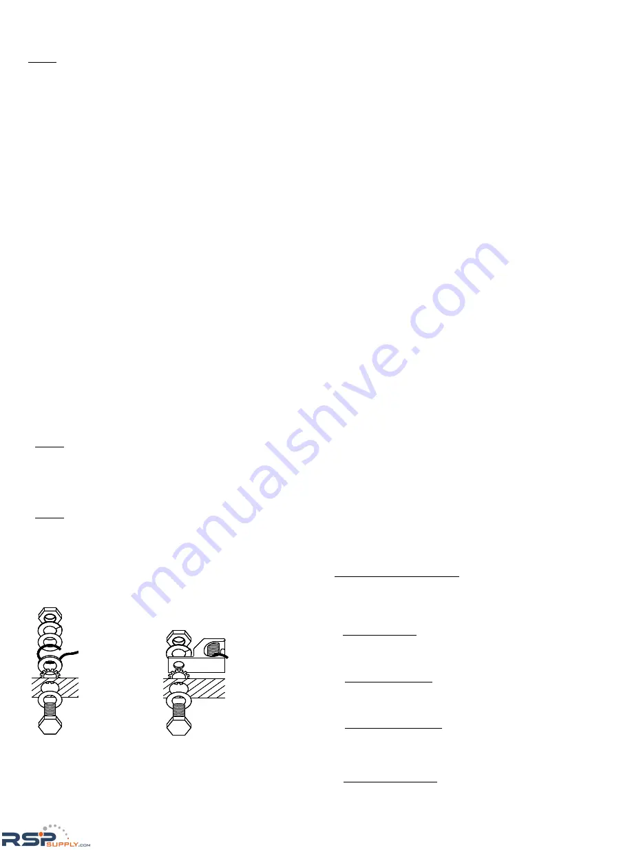
Attach the grounding conductor:
(1) to one of the .28
” (7mm) diameter holes marked
“ground” using 1/4” (6mm) stainless steel bolt. Wrap
conductor around bolt. Tighten the screws with adequate
torque (usually 62 in-lb; refer structure manufacturer
specifications).
(2) to a ground lug (manufacturer: ILSCO, model:
GBL-4DBT). The lug is attached to one of the .28
”(7mm)
diameter holes marked “ground”, using #10-32 stainless
steel bolt with 40 in-lb torque.
NOTE: A stainless steel star washer or mounting washer
nut, having contact with anodized surface of the frame,
must be employed to break through the anodized layer of
the frame extrusion and electrically connect the grounding
conductor to the conducting aluminum frame material.
NOTE: As a general rule, avoid direct contact of copper or
copper alloy ground conductors with the aluminum frame
to prevent galvanic corrosion. All ground bond securing
hardware in contact with either the aluminum module
frame and/or copper or copper alloy ground conductors
must be stainless steel.
9. BLOCKING DIODES
In systems utilizing a battery, blocking diodes are typically
placed between the battery and PV module output to
prevent battery from discharging at night. The PV module is
made of polycrystalline cells with high electrical “back flow”
resistance to nighttime battery discharging. As a result, the
PV modules do not contain a blocking diode when shipped
from the factory. Most PV charge regulators and inverters
incorporate a nighttime disconnect feature.
10. BYPASS DIODES
Partial shading of an individual module in a source circuit
string (i.e. two or more modules connected in series) can
cause a reverse voltage across the shaded cells within the
module. Module output current is then forced through the
shaded area by the remaining illuminated cells and other
PV modules in series with the partially shaded module(s).
The current forced through the shaded cells within the PV
module(s) causes additional module heating and severe
loss of power. All the PV modules are supplied with factory
installed (non user serviceable) bypass diodes.
The purpose of bypass diodes is to provide a low-resistance
current path around the shaded cells
,
thereby minimizing
PV module heating and array current losses.
The PV module employs bypass diodes that have:
・
Rated Average Forward Current [I
F(AV)
]
Above
maximum system current at highest PV module
operating temperature.
・
Rated Repetitive Peak Reverse Voltage [V
RRM
]
Above
maximum system voltage at lowest PV module
operating temperature.
11. MAINTENANCE
The PV module is designed for long life and requires very
little maintenance. Under most weather conditions, normal
rainfall is sufficient to keep the module glass surface clean.
If dirt build-up becomes excessive, clean the glass surface
only with a soft cloth using mild detergent and water. USE
CAUTION WHEN CLEANING THE BACK SURFACE OF
THE PV MODULE TO AVOID PENETRATING BACK
SHEET. PV modules that are mounted flat (0
°
tilt angle)
should be cleaned more often, as they will not "self clean"
as effectively as modules mounted at a 15
°
tilt or greater.
Once a year, check the general condition of the wiring and
check to be sure that mounting hardware is tight. Loose
connections may result in a damaged module or array.
KYOCERA Solar Group Sales Office
KYOCERA Corporation
Corporate Solar Energy Group
6 Takeda Tobadono-cho Fushimi-ku, Kyoto 612-8501, Japan
Phone: 81-75-604-3476
Fax: 81-75-604-3475
http://www.kyocera.com/
KYOCERA Solar, Inc.
7812 East Acoma Drive, Scottsdale, AZ 85260, U.S.A.
Phone: 1-480-948-8003 or 1-800-223-9580
Fax: 1-480-483-6431
http://www.kyocerasolar.com/
KYOCERA Solar Pty Ltd.
Level 3, 6-10 Talavera Road, North Ryde NSW 2113, Australia
Phone: 61-2-9870-3946
Fax: 61-2-9888-9673
http://www.kyocerasolar.com.au/
KYOCERA Solar do Brasil Ltda.
Av. das Americas, 20007
– Bloco 2 – Salas (rooms) 105 to 108,
Rio de Janeiro, 22790-851, Brazil
Phone: 55-21-3724-3900
Fax: 55-21-3724-3911
http://www.kyocerasolar.com.br/
Nut
Spring washer
Flat washer
Star washer
Ground lug
Bolt
Aluminum
frame
Nut
Spring washer
Flat washer
Star washer
Ground lug
Bolt
Aluminum
frame
Nut
Spring washer
Flat washer
Ground conductor
Cup washer
Star washer
Aluminum frame
Flat washer
Bolt
Nut
Spring washer
Flat washer
Ground conductor
Cup washer
Star washer
Aluminum frame
Flat washer
Bolt
RSPSupply - 1-888-532-2706 - www.RSPSupply.com
http://www.RSPSupply.com/p-19710-Kyocera-KD325GX-LFB-325-watt-Solar-Panel.aspx


